Power amplification apparatus for envelope modulation of high frequency signal and method for controlling the same

a technology of power amplification apparatus and high frequency signal, which is applied in the direction of amplifiers with semiconductor devices/discharge tubes, communication jamming, transmission, etc., can solve the problems of reducing power amplification efficiency, switching amplifiers cannot perform the optimal operation of low input frequency, and envelope modulators can hardly maintain high efficiency in different modes, etc., to achieve high-efficiency amplification of multi-mode input signals

Active Publication Date: 2012-07-31
SAMSUNG ELECTRONICS CO LTD
View PDF2 Cites 7 Cited by
  • Summary
  • Abstract
  • Description
  • Claims
  • Application Information

AI Technical Summary

Problems solved by technology

With the increasing complexity of communication systems and the advent of various communication protocol standards, the envelope modulator is required to operate in one or more operating frequency bands.
When operating with multiple modes, the envelope modulator can hardly maintain its high efficiency in different modes because a bandwidth and a Peak-to-Average Power Ratio (PAPR) of an input signal are different according to the modes.
In this case, if the operating frequency of the switching amplifier is optimized for the highest input frequency, the switching amplifier can no longer perform the optimal operation for the low input frequency, thus reducing the power amplification efficiency.
Designed to be optimized for only one communication mode, communication protocol standard, or operating frequency, the conventional envelope modulator may not ensure its high efficiency when operating with other modes or communication protocols in a system requiring multiple modes.

Method used


Image

  • Power amplification apparatus for envelope modulation of high frequency signal and method for controlling the same
  • Power amplification apparatus for envelope modulation of high frequency signal and method for controlling the same
  • Power amplification apparatus for envelope modulation of high frequency signal and method for controlling the same

Examples


Embodiment Construction

[0021]FIG. 1 through 5, discussed below, and the various embodiments used to describe the principles of the present disclosure in this patent document are by way of illustration only and should not be construed in any way to limit the scope of the disclosure. Those skilled in the art will understand that the principles of the present disclosure may be implemented in any suitably arranged power amplification apparatus. In the following description, specific details such as detailed configuration and components are merely provided to assist the overall understanding of exemplary embodiments of the present invention. Therefore, it should be apparent to those skilled in the art that various changes and modifications of the embodiments described herein can be made without departing from the scope and spirit of the invention. In addition, descriptions of well-known functions and constructions are omitted for clarity and conciseness.

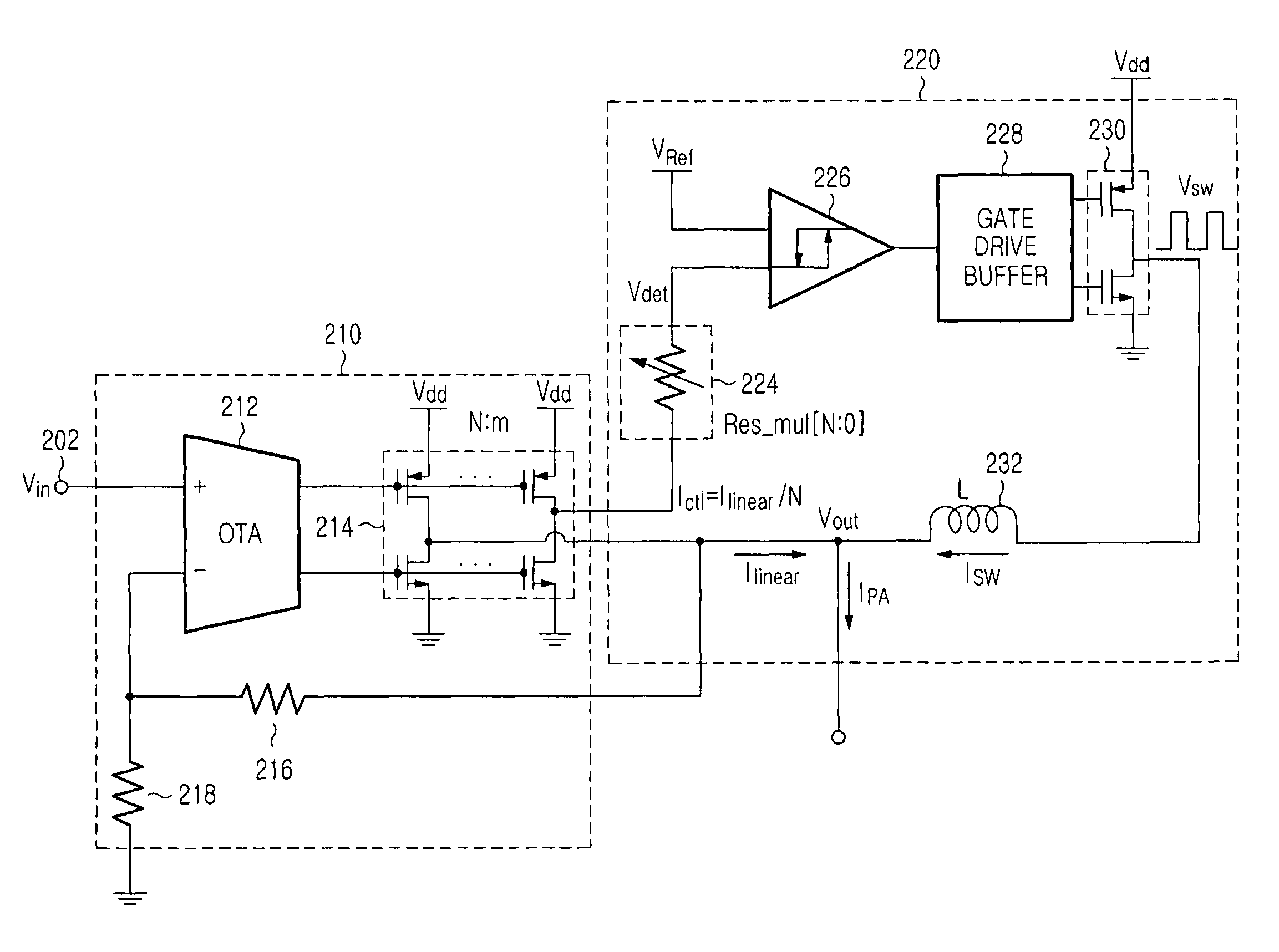
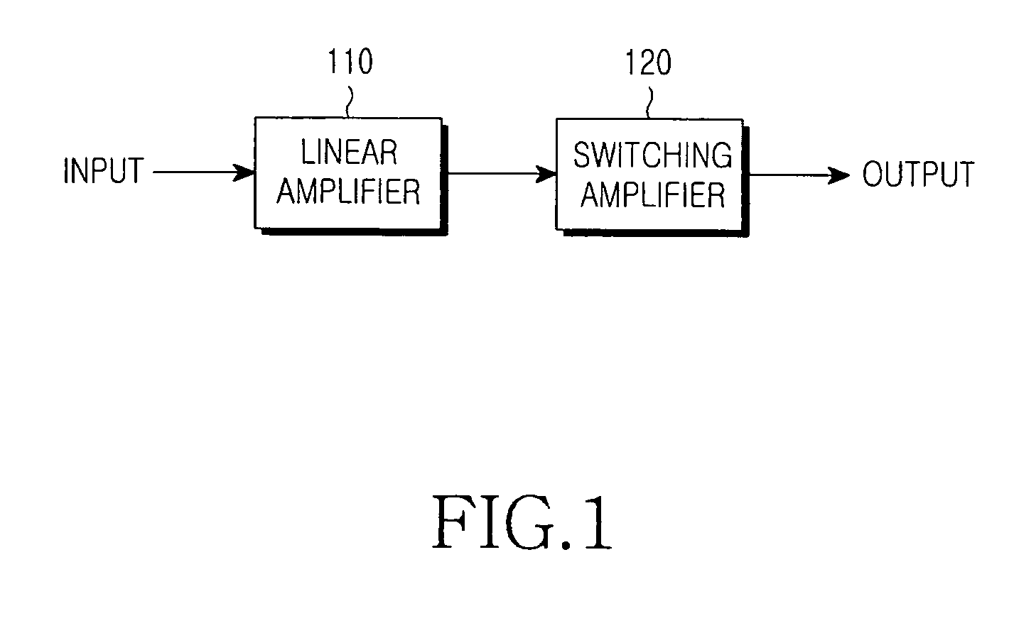
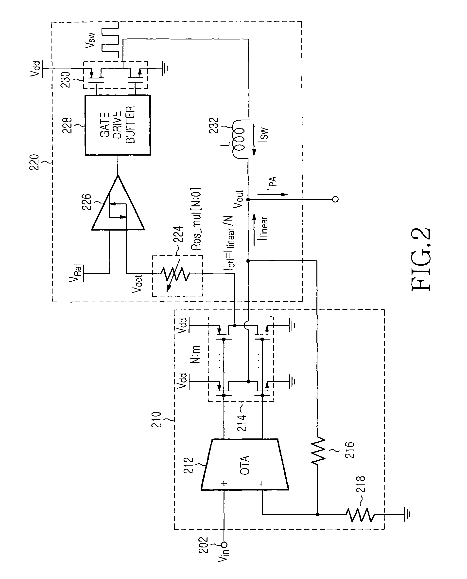
[0022]FIG. 1 illustrates the overall structure of a power...


PUM


Abstract

A power amplification apparatus and method provide for controlling envelope modulation of a Radio Frequency (RF) signal. The power amplification apparatus includes a linear amplifier configured to receive an input signal to be amplified, and generate a linear output signal for compensating for a current ripple of an amplified signal and a switch control signal having a current obtained by dividing the linear output signal by a predetermined ratio. The power amplification apparatus also includes a switching amplifier configured to receive the switch control signal through a multi-mode resistor having a variable resistance, and generate the amplified signal. The variable resistance of the multi-mode resistor determines a switching frequency representing an operating speed of the switching amplifier, and is adjusted according to a communication mode of the input signal.

Description

CROSS-REFERENCE TO RELATED APPLICATION(S) AND CLAIM OF PRIORITY[0001]The present application is related to and claims the benefit under 35 U.S.C. §119(a) of a Korean Patent Application filed in the Korean Intellectual Property Office on Nov. 10, 2009 and assigned Serial No. 10-2009-0108150, the entire disclosure of which is hereby incorporated by reference.TECHNICAL FIELD OF THE INVENTION[0002]The present invention relates generally to a Power Amplifier (PA), and more particularly, to a power amplification apparatus for envelope modulation of Radio Frequency (RF) signals and a method for controlling the same.BACKGROUND OF THE INVENTION[0003]An apparatus for performing wireless communication in a wireless communication system (for example, a communication terminal or a base station) may include an envelope modulator to amplify RF signals. The envelope modulator includes a linear amplifier and a switching amplifier. The switching amplifier supplies most power for power amplification, ...

Claims


Application Information

Patent Timeline
Patent Type & Authority Patents(United States)
IPC IPC(8): H04B1/04H04K3/00
CPCH03F3/217H03F1/0227H04B1/04H04B7/005
Inventor LEE, JAE-SUB
Owner SAMSUNG ELECTRONICS CO LTD
Why Eureka
Try Eureka