
LED module and packaging method thereof

a technology of led modules and led lamps, applied in the direction of lighting and heating apparatus, semiconductor/solid-state device details, lighting support devices, etc., can solve the problems of low popularity of led lamps, use of light control elements, and high cos

Active Publication Date: 2012-08-07
IND TECH RES INST
View PDF26 Cites 6 Cited by
  • Summary
  • Abstract
  • Description
  • Claims
  • Application Information

AI Technical Summary

Benefits of technology

This patent provides an LED module and a packaging method that allows for tilting of LED chips to achieve various lighting effects without the need for additional light control elements. The LED module includes a plurality of lead frames that are bended at a predetermined angle based on a candela distribution curve to create a tilted plane on which LED chips are fixed. The packaging method involves steps such as forming bonding metal material or metal colloidal particles on the lead frame, placing the LED chip on the bonding metal material or particles, heating up the lead frame to bond the LED chip with the lead frame, performing an interconnect bonding process on the LED chip, bending the lead frame by a predetermined angle to create a tilted plane, performing an encapsulation process and baking process on the lead frame and substrate to form the LED module, and performing a testing process on the LED module. The technical effects of this patent include improved lighting effects, reduced energy consumption, and improved thermal management.

Problems solved by technology

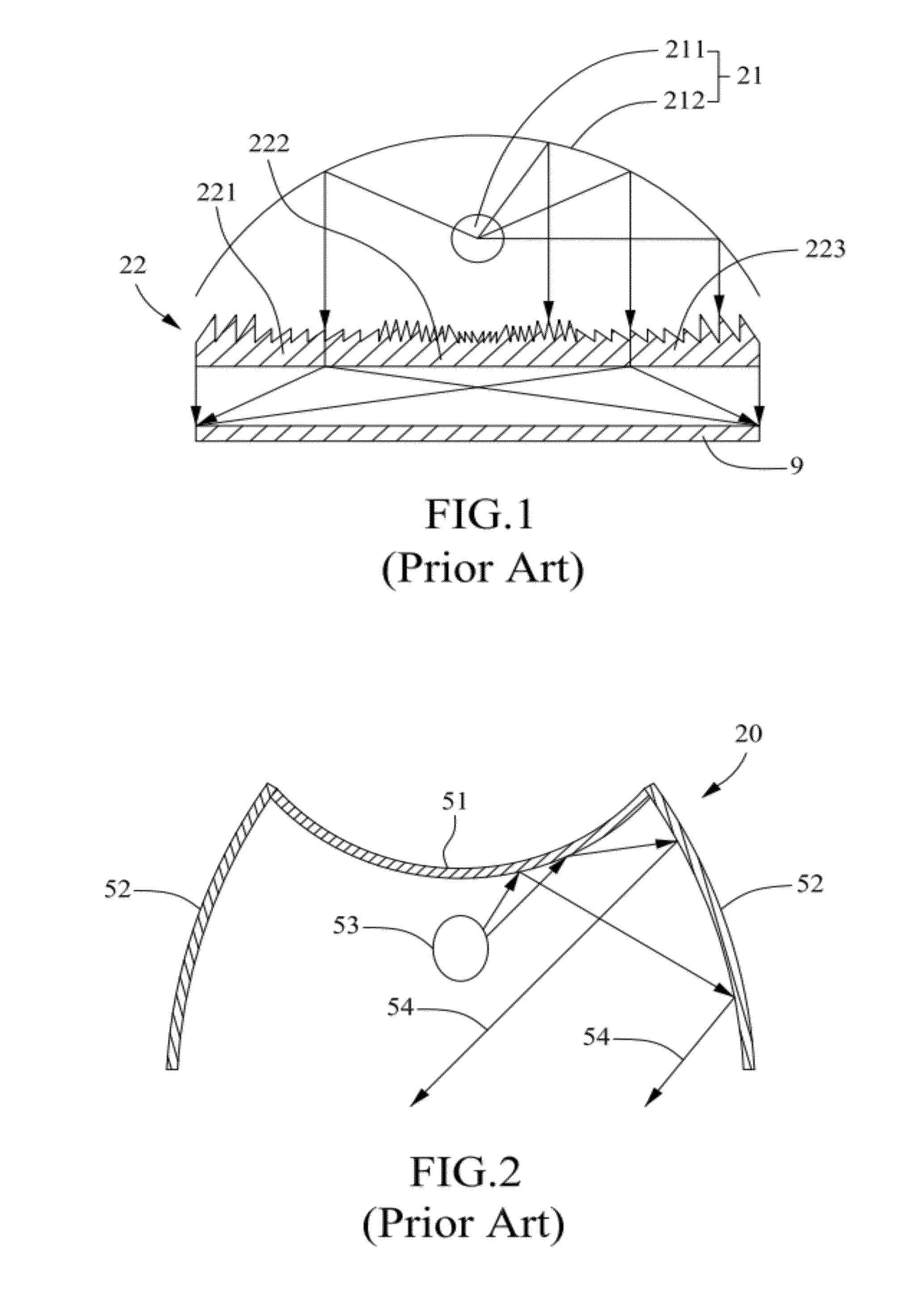
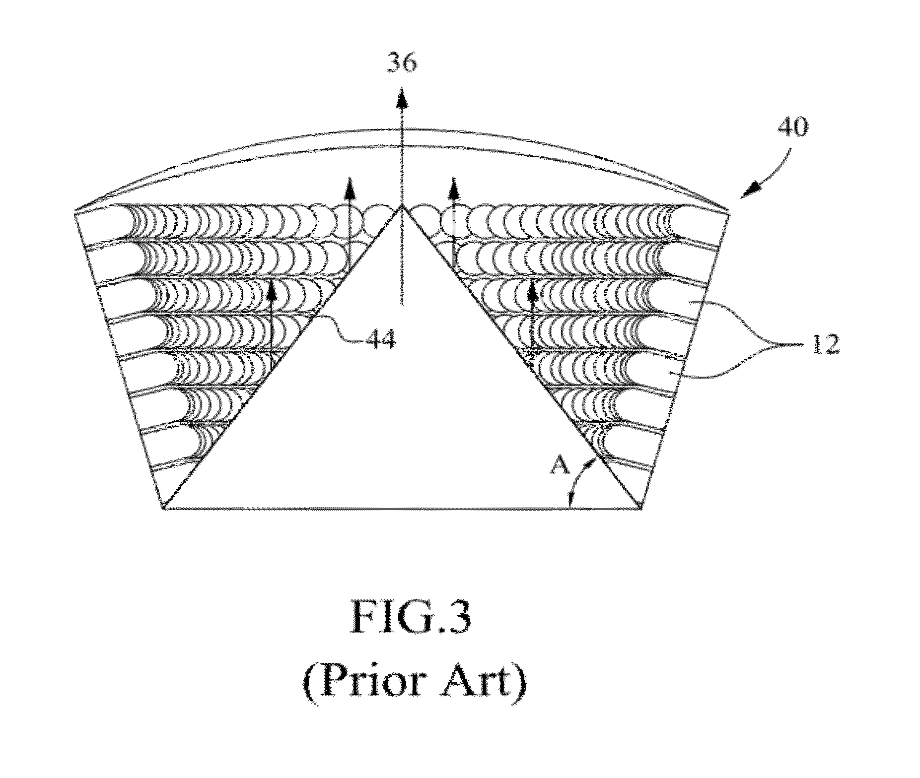
Unlike conventional lighting elements, an LED lamp generally comprises a plurality of LED ships arranged in an array because a single LED ship is small and emits light of relatively insufficient intensity.
However, it costs higher when the LED chips are arranged inclined because additional molds are required and the assembly cost rises, which leads to higher cost and lower popularity of the LED lamp.
Moreover, the use of light control elements reduces the light-emitting efficiency, which can be compensated by increased numbers of LED chips with more electricity consumed and higher lamp cost.

Method used


Image

  • LED module and packaging method thereof
  • LED module and packaging method thereof
  • LED module and packaging method thereof

Examples


first embodiment

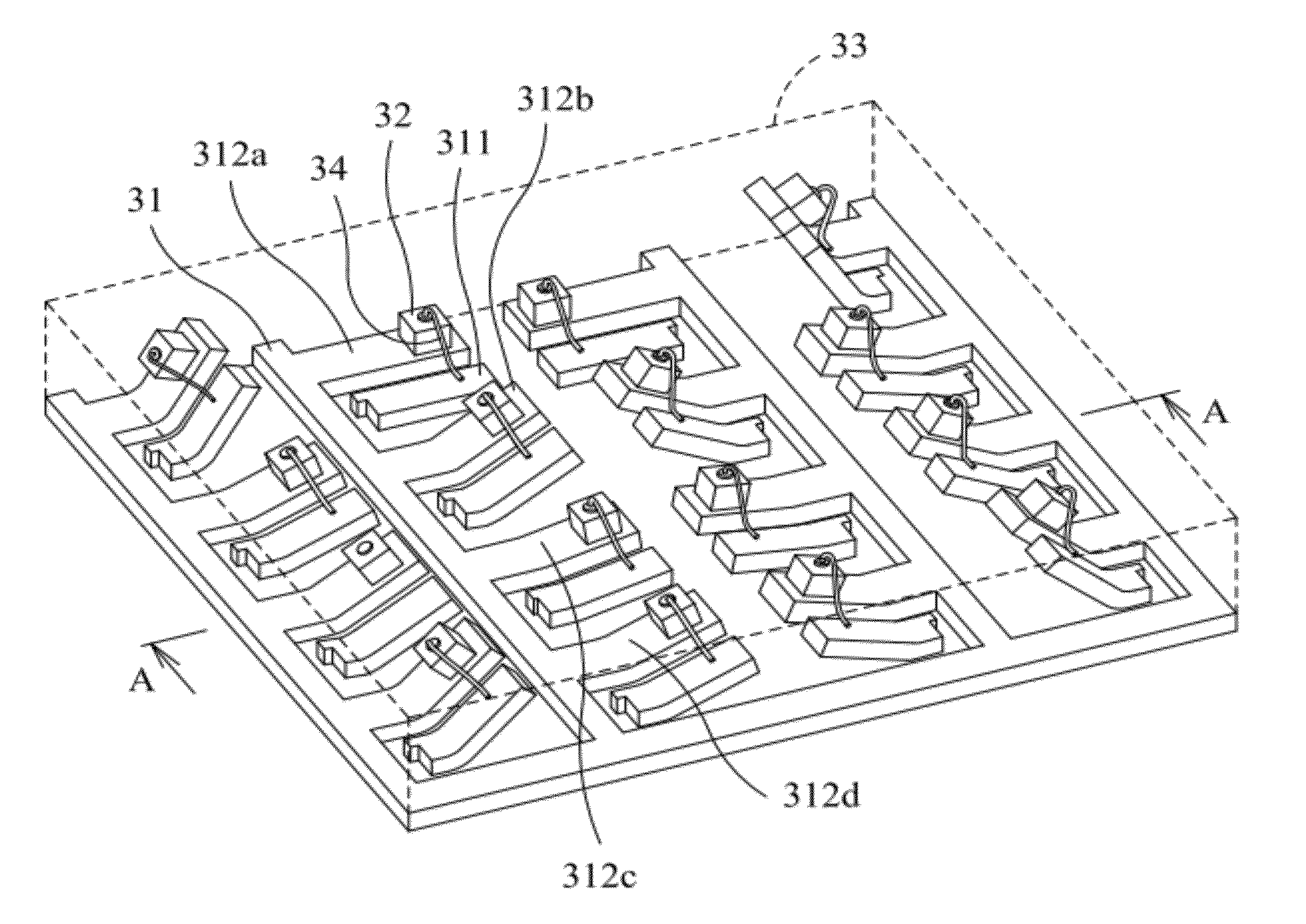
[0035]Please refer to FIG. 4, which is a cross-sectional diagram of a packaging structure for an LED module according to the disclosure. The LED module 1 comprises a plurality of lead frames 11, each being bended by a predetermined angle according to a candela distribution curve to construct a tilted plane 112; and a plurality of LED chips 12, each being fixedly disposed on the tilted plane 112 constructed by each of the lead frames 11. The lead frames 11 comprise Cu, Fe, Ni or combination thereof. The LED chips 12 comprise semiconductor materials such as GaN, GaInN, AlInGaP, AlInGaN, AlN, InN, GaInAsN and GaInPN. The LED chips 12 are sapphire-based, thin-GaN LED's or flip-chip packaged. Moreover, each of the lead frames 11 is provided with a heat sink 14 at the bottom. The lead frames 11, LED chips 12 and the heat sink 14 are further covered by a transparent encapsulant 13.

second embodiment

[0036]Please refer to FIG. 5A, which is a cross-sectional diagram of a packaging structure for an LED module according to the disclosure. FIG. 5A is different from FIG. 4 in that the tilted plane 112 is recessed to form a cup 111 having a reflective surface so that the light from the LED chip 12 is more uniform than in FIG. 4.

[0037]FIG. 5B is a cross-sectional diagram of a packaging structure for an LED module according to a third embodiment of the disclosure; and FIG. 5C is a three-dimensional diagram of a packaging structure for an LED module according to a fourth embodiment of the disclosure. In FIG. 5B and FIG. 5C, a cup 113 having a reflective surface protrudes from the tilted plane 112 so that the light from the LED chip 12 is more uniform. The cup 113 can be formed by injection molding.

[0038]Please refer to FIG. 6, which is a flowchart of a LED packaging method according to a first embodiment of the disclosure. Meanwhile, please refer to FIG. 7 for a cross-sectional diagram o...


PUM


Abstract

A light-emitting diode (LED) module and an LED packaging method. As the LED module is packaged under the consideration of candela distribution, each of the lead frames of the LED chips packaged in the LED module is bended for tilting the LED chips by different angles to exhibit various lighting effects. Meanwhile, in the LED packaging method, a plurality of LED chips can be loaded on board rapidly and aligned by one operation to result in less deviation in the candela distribution curve.

Description

TECHNICAL FIELD[0001]The disclosure generally relates to an LED module and a packaging method thereof and, more particularly, to an LED module and an LED packaging method, wherein the LED module is packaged under the consideration of candela distribution and each of the lead frames of the LED chips packaged in the LED module is bended for tilting the LED chips by different angles to exhibit various lighting effects without using additional light control elements. Meanwhile, in the LED packaging method, a plurality of LED chips can be loaded on board rapidly and aligned by one operation to result in less deviation in the candela distribution curve.TECHNICAL BACKGROUND[0002]In the field of lighting, light-emitting diodes (LED's) are becoming more and more popular because they are advantages as being compact, high-efficiency, durable and diverse in colors. Unlike conventional lighting elements, an LED lamp generally comprises a plurality of LED ships arranged in an array because a sing...

Claims


Application Information

Patent Timeline
Patent Type & Authority Patents(United States)
IPC IPC(8): F21S4/00F21V21/00H01L23/48
CPCF21K9/00F21V19/02F21Y2101/02H01L25/0753H01L33/62H01L2224/45124H01L2224/45144H01L2224/45147H01L2924/00H01L2224/48091H01L2224/48247H01L2924/00014H01L2924/01322H01L2924/01047F21Y2115/10F21Y2107/50H01L2224/29339H01L2924/01014F21S2/005
Inventor LIN, JIAN-SHIANLAI, CHIEH-LUNGLIN, HSIU-JENLU, WENG-JUNGHUANG, YI-PINGTU, YA-CHUN
Owner IND TECH RES INST
Learn More