Eureka AIR delivers breakthrough ideas for toughest innovation challenges, trusted by R&D personnel around the world.

System and interface for monitoring information technology assets

a technology of information technology assets and interfaces, applied in the field of system and interfaces for monitoring information technology assets, can solve the problems of inability to comprehend the use, performance and cost of intertwined systems, internal hardware, software and traps typically used in the prior art to gather data, and the allocation of network resources, so as to achieve global enterprise visibility of the use, performance and cost of these intertwined systems

Inactive Publication Date: 2012-08-07
DYNATRACE
View PDF11 Cites 7 Cited by
  • Summary
  • Abstract
  • Description
  • Claims
  • Application Information

AI Technical Summary

Benefits of technology

[0008]Another object of the present invention is to provide an IT analytics system that utilizes embedded network protocols and the flexibility and reliability of the public Internet to collect and disseminate client data.
[0009]A further object of the present invention is to provide an IT analytics system that is completely maintained and managed, and thus does not require a client to purchase, install, or maintain any software, agents, or plug-ins.
[0010]Another object of the present invention is to provide an IT analytics system that allows a client to retain complete control over its network.
[0012]Yet another object of the present invention is to provide an IT analytics system that offers standardized device and interface statistics across disparate networks to enable the client to evaluate Service Level Agreements (SLAs), device performance, bandwidth utilization, and to aid the client in strategic planning.
[0015]Another object of the present invention is to provide an IT analytics system that delivers a real-time view of the performance of Wireless Access Point (WAP) equipment, including device availability, wireless traffic statistics over monitored equipment, wireless signal strength, wireless Quality of Service (QOS), and data about remote wireless users to ensure that sufficient upstream bandwidth exists to support cost effective provisioning of the equipment needed to power the wireless networks.
[0019]A further object of the present invention is to provide an IT analytics system that is scalable and cost-effective.

Problems solved by technology

As a result, global networks have been managed locally without a clear picture of performance, operational requirements, the allocation of network resources, and affiliated costs across multiple Internet Service Providers (ISPs).
Further, the internal hardware, software and traps, typically used in the prior art to gather data has only limited out-of-the-box functionality to monitor, alert, analyze and report on applications, equipment and Internet Service Provider (ISP) performance and costs across diverse network segments that today make up an enterprise's global network, such as data (including Internet Protocol (IP)), wireless (including Wireless Access Point (WAP) access and equipment), voice (including Voice over Internet Protocol (VoIP)) and Virtual Private Networks (VPNs).
As a result, executives and operational personnel responsible for these various IT assets have lacked global enterprise visibility to comprehend the use, performance and costs of these intertwined systems.

Method used


Image

  • System and interface for monitoring information technology assets
  • System and interface for monitoring information technology assets
  • System and interface for monitoring information technology assets

Examples


Embodiment Construction

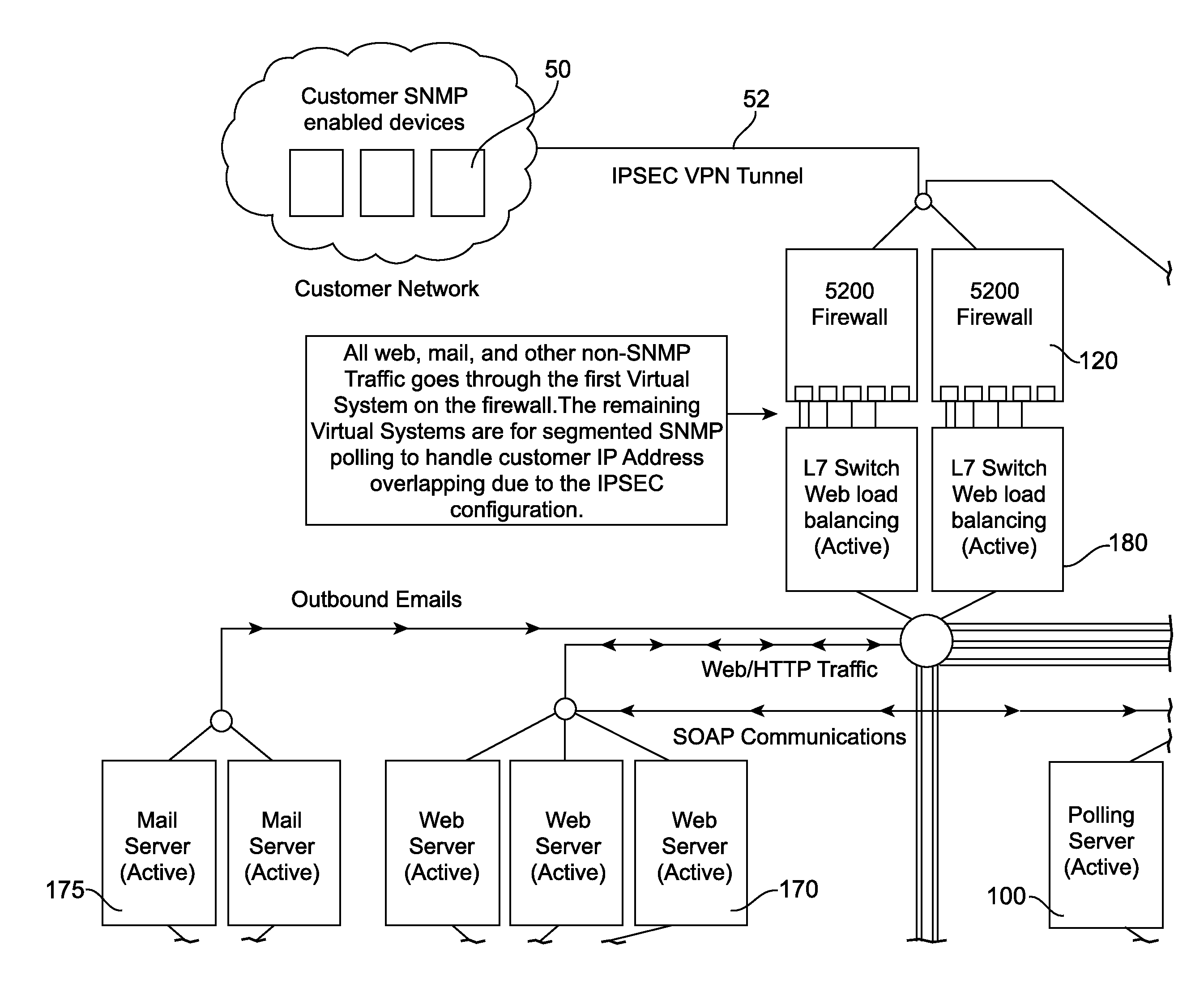
[0103]FIG. 9 provides a high-level architecture of a data network monitoring and management system in an embodiment of the invention. Referred to as the Platform or Platform process in embodiments, the present invention provides a system and method of enabling communications between a network device and application servers, a storage server computer and an end-user workstation.

[0104]Devices monitored by the system have SNMP read permissions enabled and be visible to the polling servers by establishing a VPN link and routing between the client and the datacenter.

[0105]User access to the Platform user interface is through a standards compliant web based interface; the user can use a variety of standard web browsers from their client machine. In one embodiment, the Platform User Interface (UI) requires a minimum of Internet Explorer 5.5, NetScape 6.0, Mozilla [1.6], and preferably at least Internet Explorer 6.0. It is appreciated, however, that alternative versions of the aforementione...


PUM


Abstract

An application service provider (ASP)-based interface and system for analyzing performance and costs of respective enterprise information technology assets from the correlation of metrics data of enterprise SNMP-enabled devices.

Description

CROSS-REFERENCE TO RELATED APPLICATIONS[0001]This application is a continuation of U.S. application Ser. No. 11 / 167,057 filed on Jun. 24, 2005 which is a continuation-in-part of U.S. application Ser. No. 11 / 120,326 filed May 2, 2005, which claims the benefit of U.S. Provisional Application No. 60 / 568,837 filed May 6, 2004 and U.S. Provisional Application No. 60 / 581,304 filed Jun. 18, 2004, and which is a continuation-in-part of U.S. application Ser. No. 10 / 826,548 filed Apr. 16, 2004, which is a continuation of U.S. patent application Ser. No. 10 / 764,276, filed Jan. 23, 2004, which claims the benefit of U.S. Provisional Application No. 60 / 442,021, filed Jan. 23, 2003, U.S. Provisional Application No. 60 / 442,023, filed Jan. 23, 2003, U.S. Provisional Application No. 60 / 453,686, filed Mar. 11, 2003, and U.S. Provisional Application No. 60 / 492,472, filed Aug. 5, 2003, all of which are relied on and incorporated by reference.BACKGROUND OF THE INVENTION[0002]During the past 10 years, com...

Claims


Application Information

Patent Timeline
Patent Type & Authority Patents(United States)
IPC IPC(8): G01R31/08G06F15/173
CPCG06F15/173H04L43/0817H04L41/064H04L41/22H04L41/0213
Inventor MAIOCCO, JAMES N.BELANGER, BRADLEY M.MANSELL, BRIAN E.MCCASKEY, JOHN A.
Owner DYNATRACE
Why Eureka
Eureka Blog
Learn More