Electric-electronic toothbrush

a toothbrush and electric current technology, applied in the field of electric-electronic toothbrushes, can solve the problems of uneven electric current flowing within the user's oral cavity, and achieve the effect of absorbing the vibration of the shaft and maintaining the superior effect of tooth plaque removal

Inactive Publication Date: 2012-08-14
PANASONIC CORP
View PDF13 Cites 11 Cited by
  • Summary
  • Abstract
  • Description
  • Claims
  • Application Information

AI Technical Summary

Benefits of technology

[0005]The electric-electronic toothbrush in the present invention includes a handle 10 carrying the shaft 30, an actuator 20 which is disposed within the handle and configured to vibrate the shaft along and / or about its axis, a brush head 60 connected to the shaft. The handle 10 is provided on its outer peripheral surface with a touch electrode 14 for contact with a user's hand. The brush head 60 is equipped with a brush electrode 64. The handle 10 is provided with the electric source 12 configured to generate a potential difference between the touch electrode 14 and the brush head 64, so as to flow the electric current into the user's oral cavity through his / her body for removal of tooth plaque. The shaft 30 is electrically conductive, and is coupled by way of an extendible electrically conductive coupler 50;50A to an electrically conductive member 52;13 which is connected to one of poles of the electric source 12. This configuration enables the electric current to flow from within the electric source 12 through the touch electrode 14, user's body, user's teeth, the brush head, the shaft, the electrically conductive coupler, and the electrically conductive member for the purpose of removing tooth plaque, and thereby achieving the electric toothbrush giving combination effect in the removal of tooth plaque caused by the electric current and in teeth brushing due to the vibration of the brush. This electrically conductive coupler 50;50A is secured at its one end to the shaft 30, and at the other end to the electrically conductive member 52;13 located at a predetermined position within the handle 10, so as to absorb vibration of the shaft 30. This configuration enables the shaft to vibrate without negatively affecting the electrical connection between the electric source and the shaft, stabilizing the electric connection, and thereby maintaining the superior effect in the removal of tooth plaque by a desirable electric current flowing into the user's oral cavity.
[0006]This electrically conductive coupler 50 is preferably made of an elastic material, such as a coil spring, for effectively absorbing the vibration of the shaft.
[0008]More preferably, the electrically conductive coupler 50 is disposed to have its center coincident with an axis core of the shaft 30. With this arrangement, the shaft is kept vibrating about its axis, i.e., free from being deviated therefrom, leaving no undue force which is transmitted from the electrically conductive coupler to act on the bearing, and thereby enabling to keep the shaft stably vibrating.

Problems solved by technology

However, the connecting metal part is designed to have a contact portion at its one end for sliding on the shaft, causing unevenness in the electric current flowing within the user's oral cavity by a variance in the electric resistance of the connecting portion between the shaft and the connecting metal part in response to bending of the shaft by user's force toward his / her teeth and deflection of the shaft due to vibration of the shaft during user's tooth brushing.

Method used


Image

  • Electric-electronic toothbrush
  • Electric-electronic toothbrush
  • Electric-electronic toothbrush

Examples


Embodiment Construction

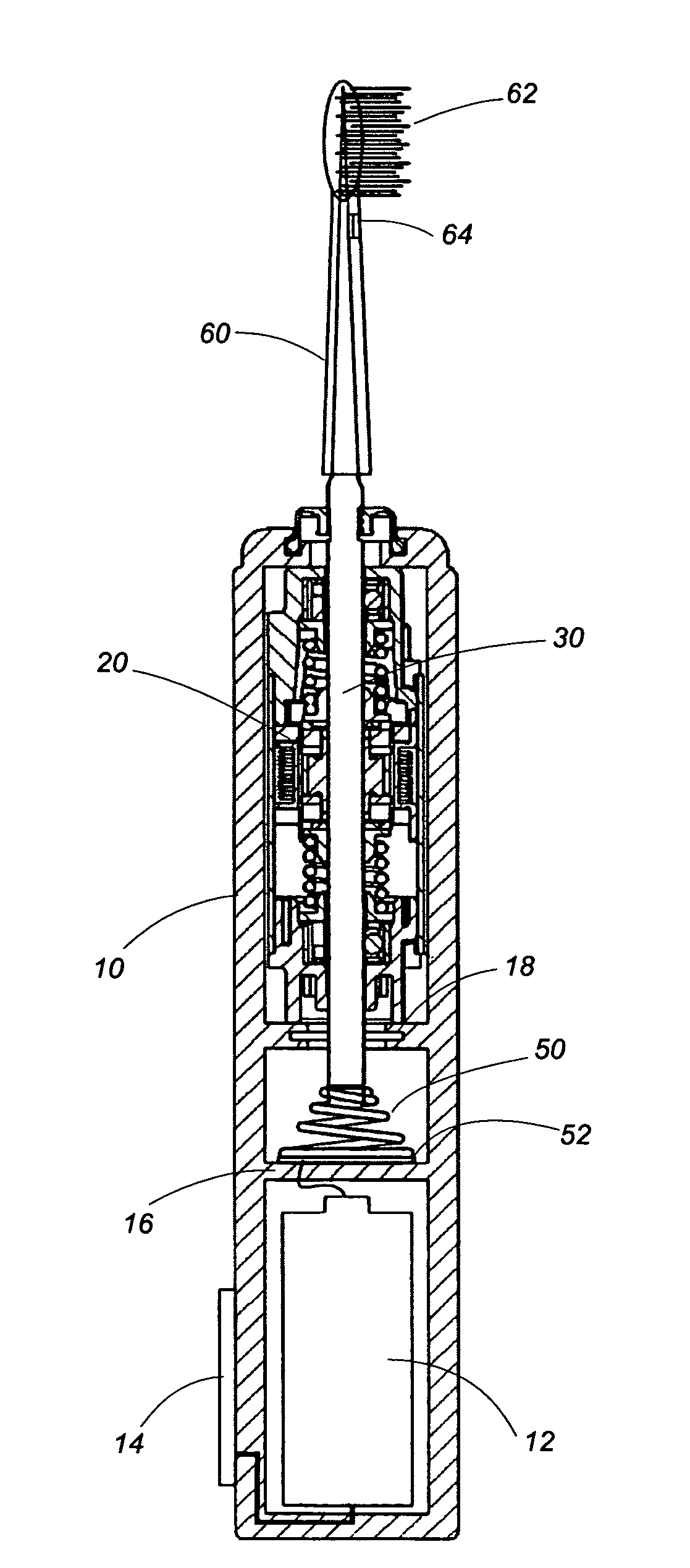
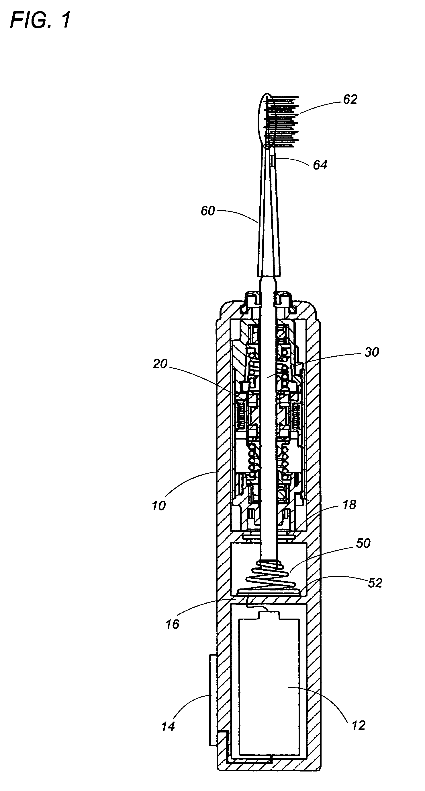
[0015]FIG. 1 shows an electric-electronic toothbrush in an embodiment of the present invention. The electric-electronic toothbrush has a cylindrical handle 10 to be grasped by a user's hand, an actuator 20 disposed within the handle 10, a shaft 30 driven to vibrate by the actuator 20, a brush head 60 detachably coupled to the shaft 30. The actuator 20 drives the shaft 30 to vibrate along its axis, so as to vibrate a brush 62 provided at a front end of the brush head 60.

[0016]The handle 10 accommodates therein a battery 12 acting as an electric source for driving the actuator 20. The shaft 30 is arranged at its front end to project out through a front end of the handle 10, so as to be coupled to the brush head 60. On a rear end portion of outer peripheral surface of the handle 10 to be in contact with a user's hand, a touch electrode 14 is disposed so as to be connected to a negative pole of the battery 12. The battery 12 is connected at its positive pole to the shaft 30 by way of an...


PUM


Abstract

An electric-electronic toothbrush carries a brush driven to vibrate, and arranged to flow an electric current into a user's oral cavity for promoting removal of tooth plaque. The electric-electronic toothbrush has a shaft driven to vibrate along and / or about an axis of the shaft, and a battery supplying the electric current. The shaft is electrically conductive to flow the electric current into a brush electrode of a brush head. The shaft is electrically connected to the battery by way of an extendible electrically conductive coupler within the handle. The electrically conductive coupler has its one end secured to the shaft, and the other end to an electrically conductive member connected to one of poles of the battery, so as to absorb the vibration of the shaft. The handle is provided on its outer peripheral surface with a touch electrode. The electric-electronic toothbrush is arranged to give predetermined electric potentials respectively to the brush electrode and the touch electrode, so as to flow a microelectric current onto the tooth surface for removal of tooth plaque during user's tooth brushing due to vibration of a brush.

Description

TECHNICAL FIELD[0001]This invention relates to an electric-electronic toothbrush with a brush driven to vibrate.BACKGROUND ART[0002]Japanese Patent Publication NO. 2560025 discloses a conventional electric toothbrush. This electric toothbrush has a handle to be grasped by user, a vibration unit accommodated within the handle for vibrating a shaft along its axis. The shaft is detachably connected to a brush head, and driven to vibrate the brush head by the vibration unit. This electric toothbrush is designed to flow a micro-electric current through user's body into portion of a user's oral cavity in contact with the brush head, for removal of tooth plaque. This electric toothbrush is equipped with a source of micro-electric current having one pole connected to a touch electrode for contact with user's hand at an outer perimeter of the handle, and the other pole connected to the electrically conductive shaft by way of a connecting metal part, so as to give a predetermined electric pot...

Claims


Application Information

Patent Timeline
Patent Type & Authority Patents(United States)
IPC IPC(8): A61C17/22
CPCA46B15/0002A46B15/0022A61C17/3445H02K33/02
Inventor SHIMIZU, HIROAKIKUNITA, TOMOHIROTANIGUCHI, SHINICHIKISHIMOTO, SUEHISAKITAGAWA, TADANOBU
Owner PANASONIC CORP
Why Eureka
Try Eureka