Device and method for the transfer of flexible flat articles

a flat article and flexible technology, applied in the field of material handling technology, can solve the problems of reducing the quality of the transfer, the complexity of the complete stabilisation device, and the relative large volume of the lateral rotor, so as to improve the quality and the security of the transfer

Inactive Publication Date: 2012-08-14
FERAG AG
View PDF9 Cites 3 Cited by
  • Summary
  • Abstract
  • Description
  • Claims
  • Application Information

AI Technical Summary

Benefits of technology

[0015]By means of this synchronised movement of the grippers the upper and the lower edge of the article during the whole time period, in which the grippers are within the transfer zone, are able to be in the same position relative to one another and to the assigned upper and lower gripper. As a result of this, in comparison longer and stable transfer phase the quality and the security of the transfer are improved.
[0016]In addition, the articles are capable of being transferred within the transfer zone without being bent or compressed. As a result once again, it is possible to make do without additional elements for the stabilisation or guidance of the article within the transfer zone. The articles within the transfer zone—up until their release by the upper gripper—essentially are being conveyed in a suspended manner. The movement of the articles within the transfer zone therefore is mainly determined by the movement of the grippers in association with the force of gravity and the inertia and flexibility of the articles.

Problems solved by technology

A disadvantage of this arrangement is the relatively large volume, which is required by the lateral rotors, as well as the complexity of the complete stabilisation device.
Because of the utilisation of the gripper wheel for the transfer between the gripper conveyor and the taking-away conveyor, the device is comparatively complex.
Because of the utilisation of the transfer system, the device is comparatively complex.

Method used


Image

  • Device and method for the transfer of flexible flat articles
  • Device and method for the transfer of flexible flat articles
  • Device and method for the transfer of flexible flat articles

Examples


Embodiment Construction

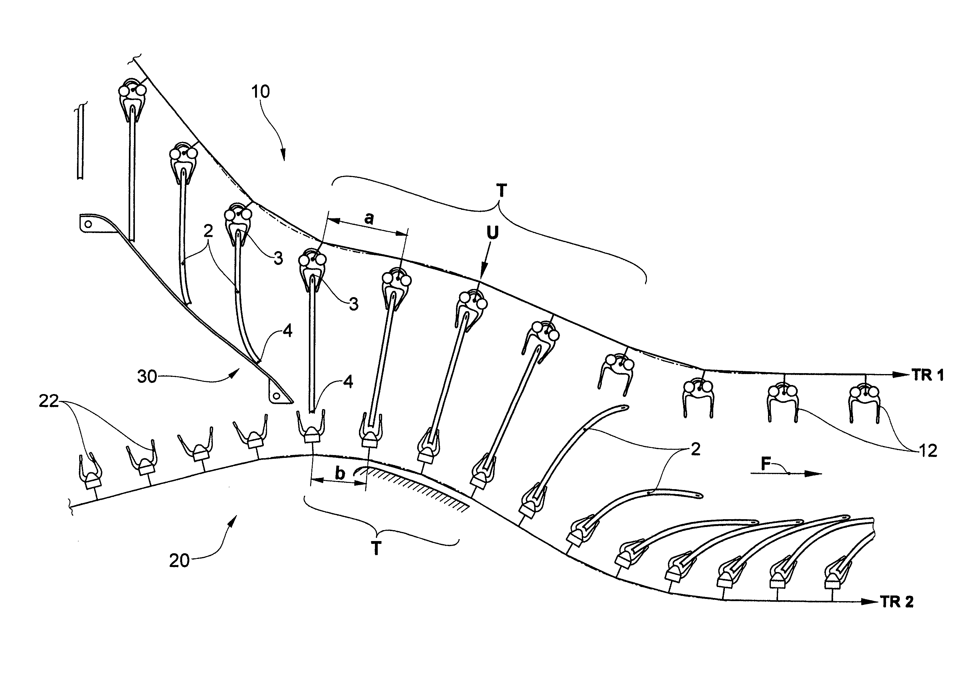
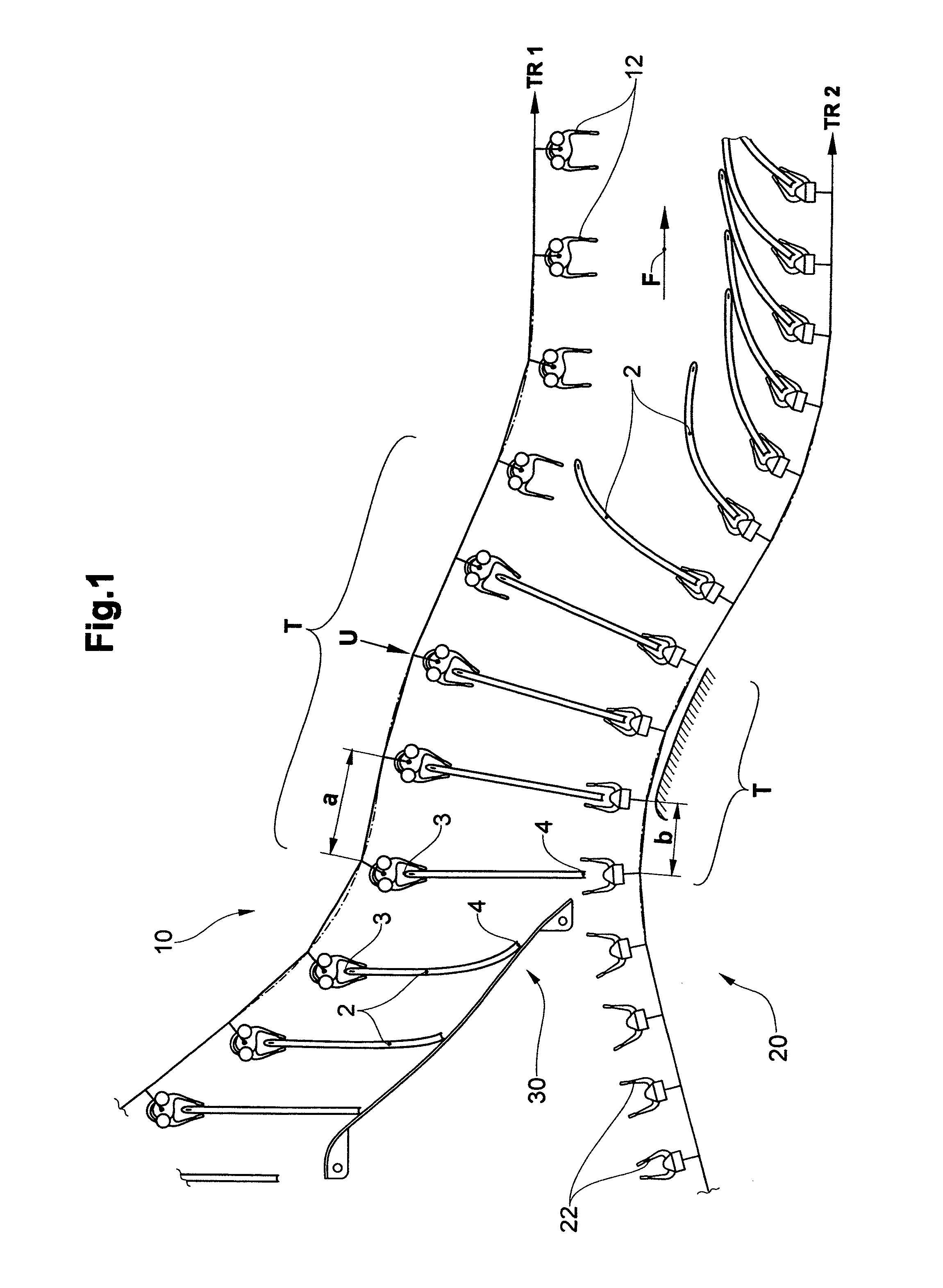
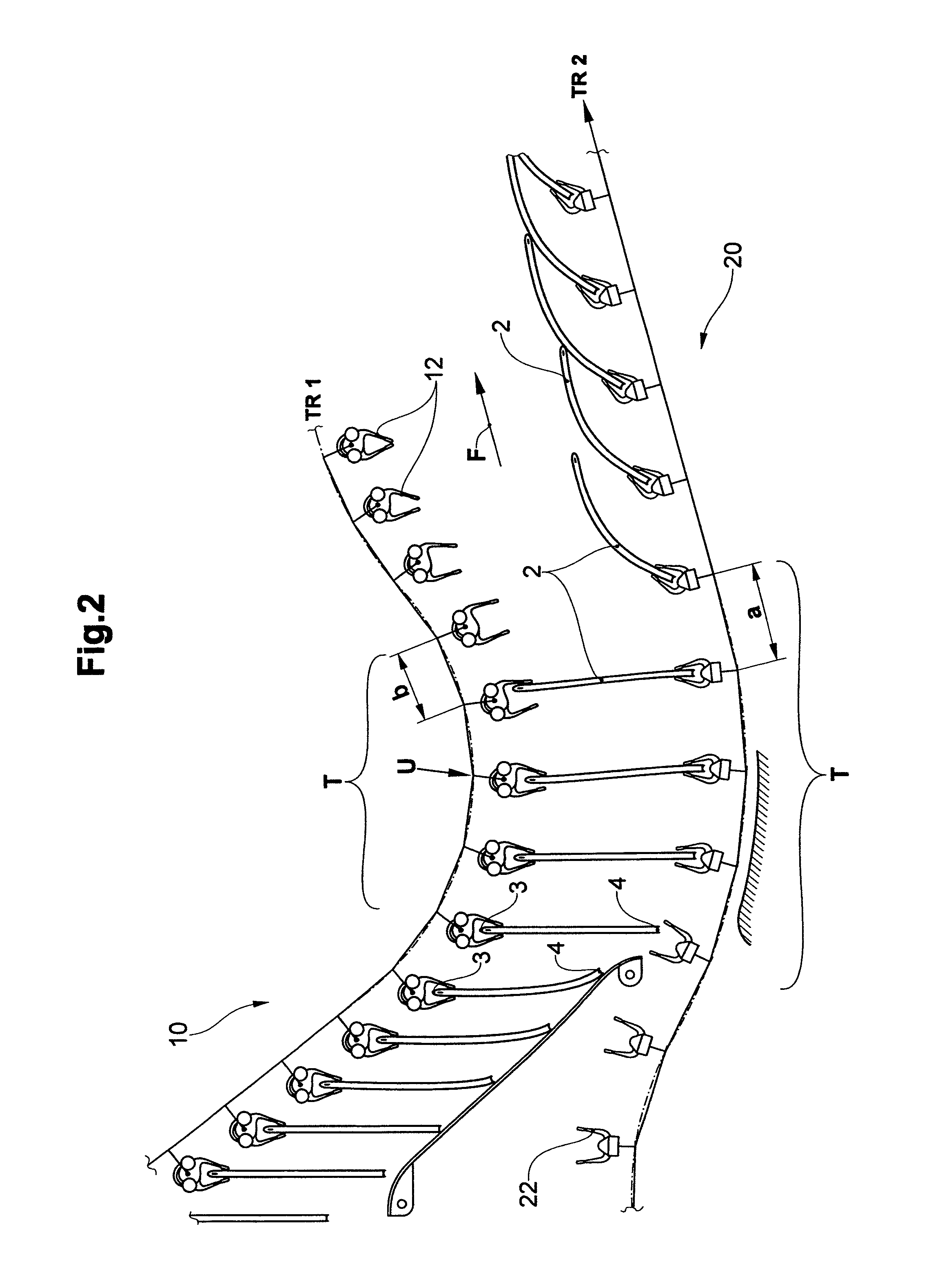
[0035]FIGS. 1 and 2 each schematically illustrate a device in accordance with the invention. In both cases there are:[0036]a first or upper gripper conveyor 10 with first grippers 12 moved along a first gripper conveyor track TR1 with regular spacing for the essentially suspended transportation of flat articles 2 in a conveying direction F by gripping a first article edge 3, and[0037]a second or lower gripper conveyor 20 with second grippers 22 moved along a second gripper conveyor track TR2 with regular spacing for taking over the articles 2 by gripping a second article edge 4, which is located opposite the first article edge 3.

[0038]Present apart from this is at least one actuation device of an as such known type, not depicted, for opening and closing the grippers 12, 22, e.g., in the form of motion control links or of other elements, which trigger the opening, resp., closing process. In preference, its own actuation device is assigned to each conveyor 10, 20.

[0039]In the transfer...


PUM

PropertyMeasurementUnit
flexibleaaaaaaaaaa
distanceaaaaaaaaaa
radiiaaaaaaaaaa

Abstract

A device and method for the transfer flexible flat articles between two conveyors. The device includes a first gripper conveyor with first grippers moved along a first gripper conveyor track for suspended transportation of the articles in a conveying direction, and a second gripper conveyor with second grippers moved along a second gripper conveyor track. Opening and closing of the grippers is controlled so that a transfer of the articles from the first to the second grippers is able to take place. In doing so, a spacing between the first grippers differs from the spacing between the second grippers such that, in a transfer zone, one gripper conveyor track, the grippers of which include the greater spacing between one another, defines a concave course, and the other gripper conveyor track, the grippers of which have the smaller spacing between one another, defines a correspondingly convex course.

Description

BACKGROUND OF THE INVENTION[0001]1. Field of the Invention[0002]The invention is situated in the field of materials handling technology and concerns a device and a method for the transfer of flexible flat articles, in particular printed products, between two conveyors, in accordance with the preamble of the corresponding independent claims.[0003]2. Description of Related Art[0004]The patent document EP-A 1834911 describes a transfer device, in the case of which individual articles are transferred by first grippers to moving in parallel second grippers. The second grippers are arranged below the first grippers. In a transfer zone the first grippers are opened, so that the articles due to the force of gravity slide into the moving along open second grippers, which thereupon are closed. For the stabilisation of the articles during the transfer, resp., in the transfer zone, a stabilisation device is provided, which comprises two helix- or spiral-shaped rotors oriented in opposite direct...

Claims


Application Information

Patent Timeline
Patent Type & Authority Patents(United States)
IPC IPC(8): B65G25/00
CPCB65H29/003B65H2301/31B65H2301/323B65H2301/44712B65H2405/552B65H2220/02B65H2220/01
Inventor KELLER, ALEX
Owner FERAG AG
Why Eureka
Try Eureka