
Extendable toolbox for a truck bed and associated method

Inactive Publication Date: 2012-08-14
CASSELTON WILLIAM
View PDF16 Cites 29 Cited by
  • Summary
  • Abstract
  • Description
  • Claims
  • Application Information

AI Technical Summary

Benefits of technology

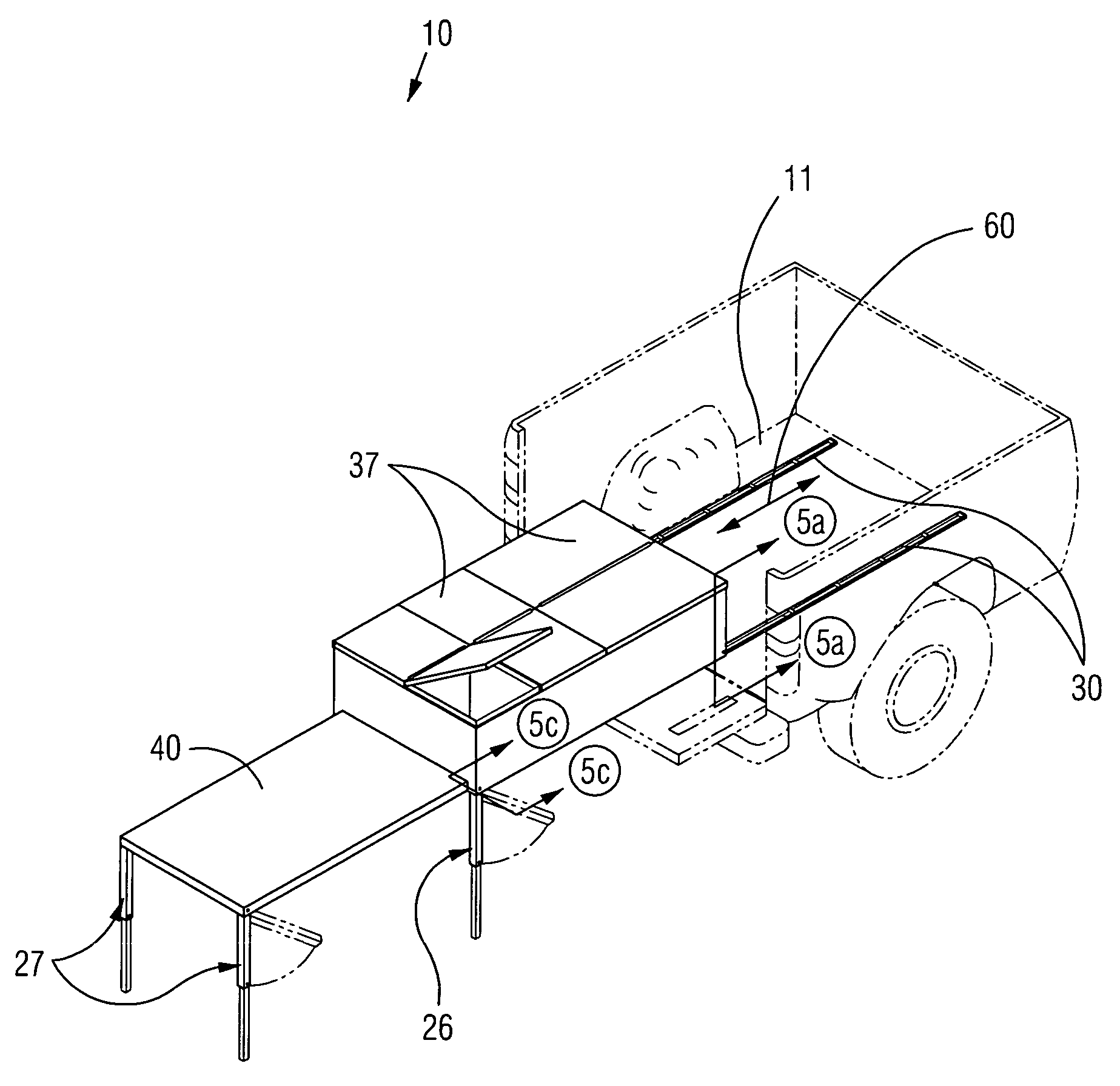
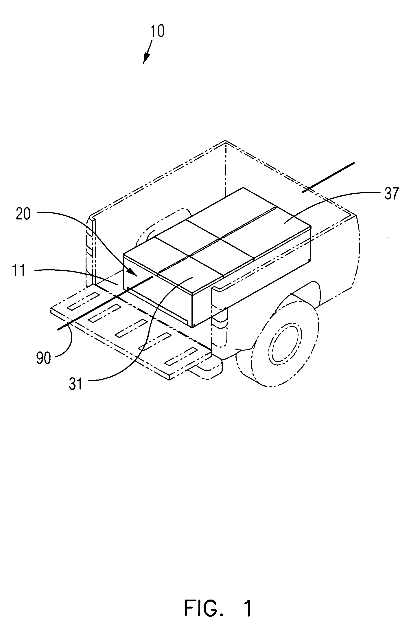
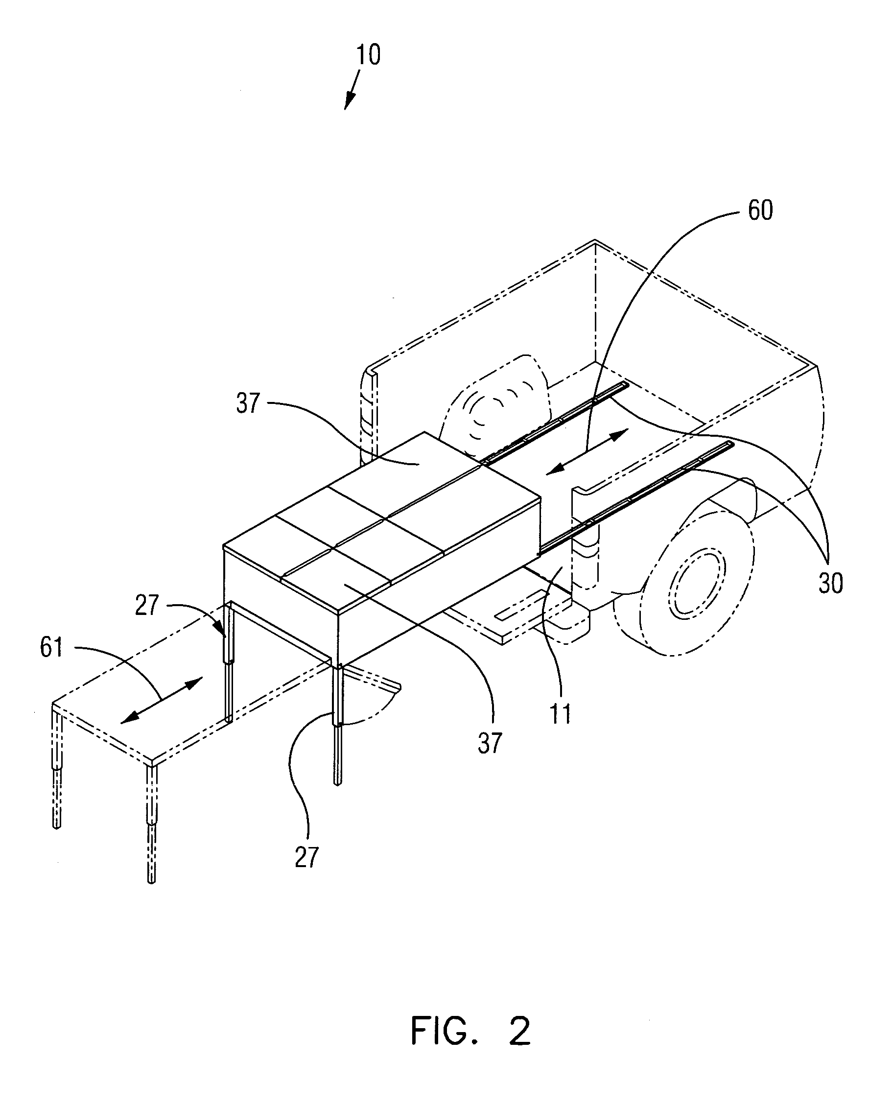
[0011]The extendable tool box may include a tool box adapted to be positioned on a truck bed and slidably reciprocated along a first horizontal travel path adapted to be aligned parallel with the truck bed. A table top may be contiguously oriented parallel with the tool box and adapted to remain disposed above the truck bed and further be slidably reciprocated along a second horizontal travel path registered parallel to the first horizontal travel path. In this way, the tool box and the table top may be independently reciprocated along the first and second horizontal travel paths respectively. The tool box may further include a bottom surface preferably having a cavity extending from a proximal end and terminating at a distal end of the tool box respectively. A sliding mechanism may be connected to the bottom surface of the tool box and thereby permit the tool box to freely reciprocate along the first horizontal travel path. Such an arrangement provides the unexpected and unpredictable advantage of extracting and retracting the tool box and table top independently of each other. As an example, a user may extend the tool box from the truck bed for accessing his tools without having to extend the table top. He may only need to extend the table top for use thereby eliminating the use of precious space unless necessary.
[0012]The table top may be removably inserted into the cavity such that the table top may contiguously lay parallel with the bottom surface of the tool box. The tool box may further include a first group of support legs and a second group of support legs pivotally mated to a bottom surface of the table top. Each of the first and second support leg groups may further be selectively and independently pivotal between horizontal and vertical positions defined parallel and orthogonal to the first and second horizontal travel paths respectively. Such an arrangement provides the unexpected and unpredictable advantage of positioning the first and second groups of support legs within the cavity in stowed position and further allowing each group of support legs to be easily extended or retracted together with the tool box by a user.
[0013]The sliding mechanism may include a plurality of rectilinear roller tracks oriented parallel to each other and adapted to be statically mated to the truck bed. A plurality of rollers may be spacedly positioned along the roller tracks such that a plurality of roller axles may passed through the rollers and further be anchored to the outer walls of the roller tracks. A plurality of spacer blocks may further be statically mated to the bottom surface of the tool box and vertically aligned above the rollers such that the spacer blocks may engage the rollers and thereby travel along the roller tracks when the tool box is reciprocated along the first horizontal travel path. The sliding mechanism may further remain laterally spaced exterior of the cavity and aligned along left and right longitudinal sides of the tool box. Such an arrangement provides the unexpected and unpredictable advantage of allowing a user to easily extend or retract the heavy tool box with minimum effort by having the spacer blocks slide over the rollers smoothly.
[0014]The sliding mechanism may further include a plurality of pin sleeves formed through the spacer blocks and oriented parallel to the roller axles and a plurality of rectilinear pivot pins positioned through corresponding support legs of the first support leg group and the spacer blocks respectively. In this way, each of the corresponding support legs may be independently pivoted while each of the spacer block remains at a statically fixed position. The pivot pins may further be rotatably situated within the pin sleeves. Such an arrangement provides the unexpected and unpredictable advantage of using the spacer block as a sliding member as well as acting as a support structure for the tool box without having to add additional weight bearing structures to support the tool box.
[0015]In one embodiment, the tool box may further include a plurality of storage compartments arranged on left and right longitudinal sides of the tool box and equidistantly offset along a central longitudinal length of the tool box respectively. The table top may be situated subjacent to the storage compartments. Such an arrangement provides the unexpected and unpredictable advantage of distributing similar contents of the tool box into specific compartments for easy retrieval and further allows for a balanced distribution of weight to the entire tool box such that the tool box may be extracted and retracted with ease by any user.
[0016]In one embodiment, the first and second support leg groups may be telescopically adjustable between extended and retracted positions respectively. The support legs may include an outer leg tube and an inner leg tube. A spring lock clip may further be used to lock the outer and inner leg tubes statically when in extended position. Such a space saving arrangement provides the unexpected and unpredicted advantage of optimizing the usage of limited space within the cavity when stowing the support leg groups.

Problems solved by technology

However, accessing the toolbox is often a problem for many due to the height and depth limitations from only being able to reach the contents from the side of the truck.
In addition, the weight of some tools and the need to clamber up and down a truck bed may be difficult for persons who are not physically in good shape or older workers.

Method used


Image

  • Extendable toolbox for a truck bed and associated method
  • Extendable toolbox for a truck bed and associated method
  • Extendable toolbox for a truck bed and associated method

Examples


Embodiment Construction

[0031]The present invention will now be described more fully hereinafter with reference to the accompanying drawings, in which a preferred embodiment of the invention is shown. This invention may, however, be embodied in many different forms and should not be construed as limited to the embodiment set forth herein. Rather, this embodiment is provided so that this application will be thorough and complete, and will fully convey the true scope of the invention to those skilled in the art. Like numbers refer to like elements throughout the figures.

[0032]The apparatus of this invention is referred to generally in FIGS. 1-7 by the reference numeral 10 and is intended to provide an extendable tool box. It should be understood that the extendable tool box 10 may be used to store and access tools and supplies on a truck bed and other different types of vehicles having recessed niches.

[0033]Referring generally to FIGS. 1-7, the extendable tool box 10 may include a tool box 20 adapted to be p...


PUM


Abstract

An extendable tool box includes a tool box, a table top and support legs. The tool box may be slidably reciprocated along a first horizontal travel path aligned parallel with the truck bed. The table top may be contiguously oriented parallel with the tool box and slidably reciprocated along a second horizontal travel path registered parallel to the first horizontal travel path. The tool box may include a bottom surface having a cavity whereby the table top may be stowed. A sliding mechanism may be connected to the bottom surface of the tool box and may permit the tool box to freely reciprocate along the first horizontal travel path. The support legs may be telescopically adjustable between extended and retracted positions. The tool box may include a plurality of storage compartments arranged on left and right longitudinal sides and equidistantly offset along a central longitudinal length of the tool box.

Description

CROSS REFERENCE TO RELATED APPLICATIONS[0001]Not Applicable.STATEMENT REGARDING FEDERALLY SPONSORED RESEARCH OR DEVELOPMENT[0002]Not Applicable.REFERENCE TO A MICROFICHE APPENDIX[0003]Not Applicable.BACKGROUND OF THE INVENTION[0004]1. Technical Field[0005]This invention relates to vehicle tool boxes and, more particularly, to an extendable tool box for providing users with an easy and convenient means of accessing their tools and supplies on a truck bed without the need to climb into their truck bed.[0006]2. Prior Art[0007]With sales at an all-time high, the popularity of the pick-up style truck as an everyday vehicle is more wide spread than it ever has been. Their utility and convenience in hauling items coupled with the availability of luxury interiors and extended cab space have made the pickup a popular alternative to other vehicles. The availability of aftermarket accessories also enhances the attractiveness of pickup trucks as well. Perhaps one of the most common accessories ...

Claims


Application Information

Patent Timeline
IPC IPC(8): B60R9/06B60R7/02
CPCB60R9/065B60R11/06
Inventor CASSELTON, WILLIAM
Owner CASSELTON WILLIAM
Learn More