
System and method for reducing viscous force between a fluid and a surface

a technology of viscous force and fluid, applied in the field of viscous drag, can solve the problems of reducing the efficiency of an object moving through a fluid as friction drag or viscous drag, affecting the forward motion of the aircraft, increasing maintenance labor and costs, etc., and reducing the viscous drag of the fluid on the surface.

Active Publication Date: 2012-08-14
THE BOEING CO
View PDF2 Cites 8 Cited by
  • Summary
  • Abstract
  • Description
  • Claims
  • Application Information

AI Technical Summary

Benefits of technology

The patent describes a metamaterial that can be used to reduce viscous drag on surfaces moving through fluids such as air or water. The metamaterial has a magnetic permeability that reverses the attractive force between the surface and the fluid, creating a repulsive force that reduces the drag. This metamaterial can be applied to various surfaces, such as airplanes, boats, and turbines, to increase efficiency and decrease fuel consumption. It can also be used in space and on land vehicles. Overall, the patent provides a passive solution to viscous drag reduction that does not require active components.

Problems solved by technology

A major contributor to the inefficiency of an object moving through a fluid is the friction drag or viscous drag that occurs at the boundary layer of the object.
In another example, a vehicle such as an aircraft moving through the air is subjected to friction drag or viscous drag at the boundary layer of the vehicle / air interface which tends to impede forward motion of the aircraft.
Unfortunately, the application of suction at the pores requires an active vacuum system.
As may be appreciated, the addition of an active vacuum system often results in a heavier system that may result in increased maintenance labor and costs.
Grooves or riblets are not intended to reduce drag and may slightly increase viscous drag due to the additional surface area of the lifting surface as a result of the grooves or riblets.

Method used


Image

  • System and method for reducing viscous force between a fluid and a surface
  • System and method for reducing viscous force between a fluid and a surface
  • System and method for reducing viscous force between a fluid and a surface

Examples


Embodiment Construction

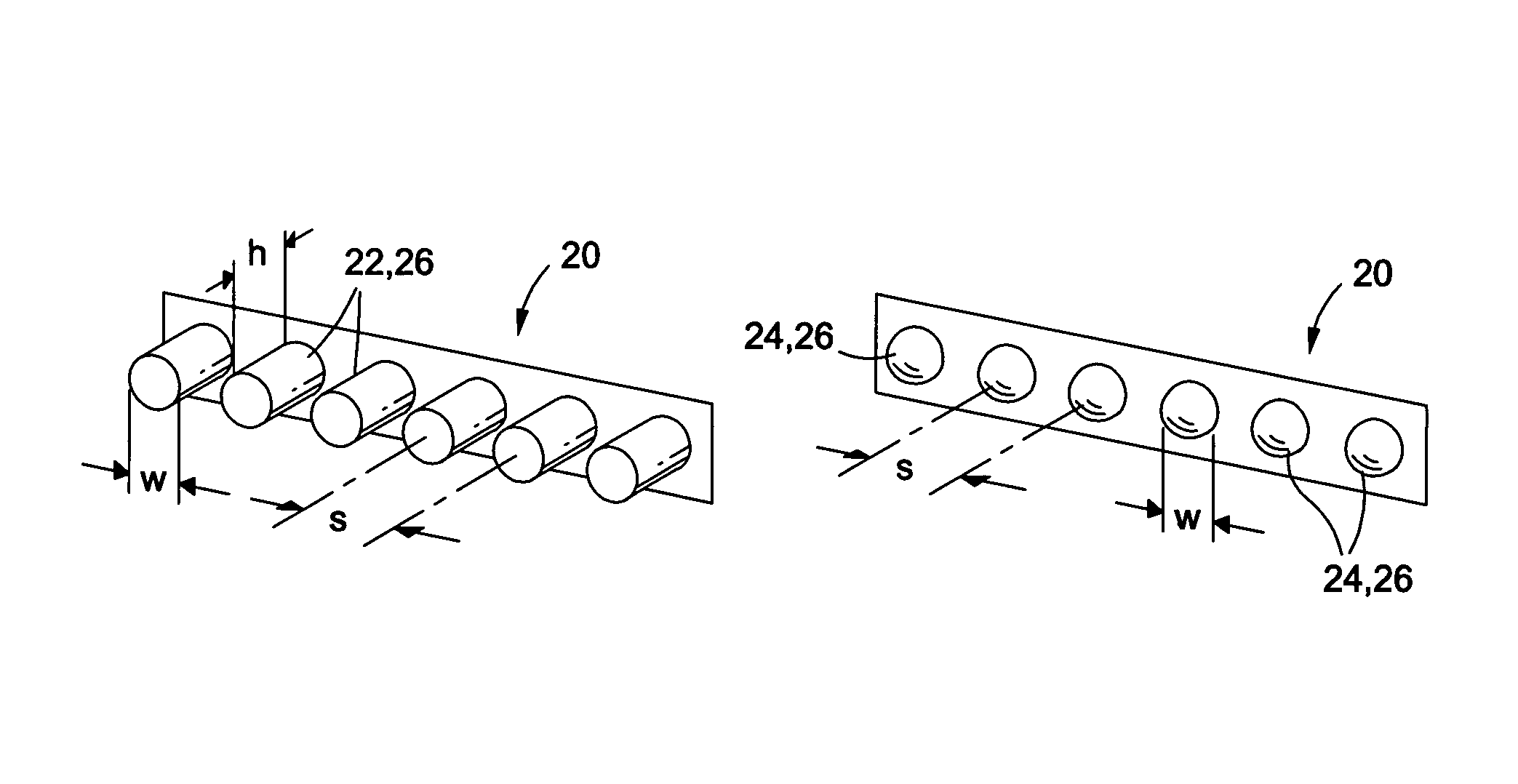
[0031]Referring now to the drawings wherein the showings are for purposes of illustrating preferred and various embodiments of the disclosure only and not for purposes of limiting the same, FIGS. 1-5C illustrate various aspects of the embodiments of the invention for reducing viscous drag of a surface moving through a fluid by exploiting properties of a metamaterial that enable, among other capabilities, the reduction, elimination, and / or reversal of the attractive forces that exist between atoms and molecules of a fluid and a surface.

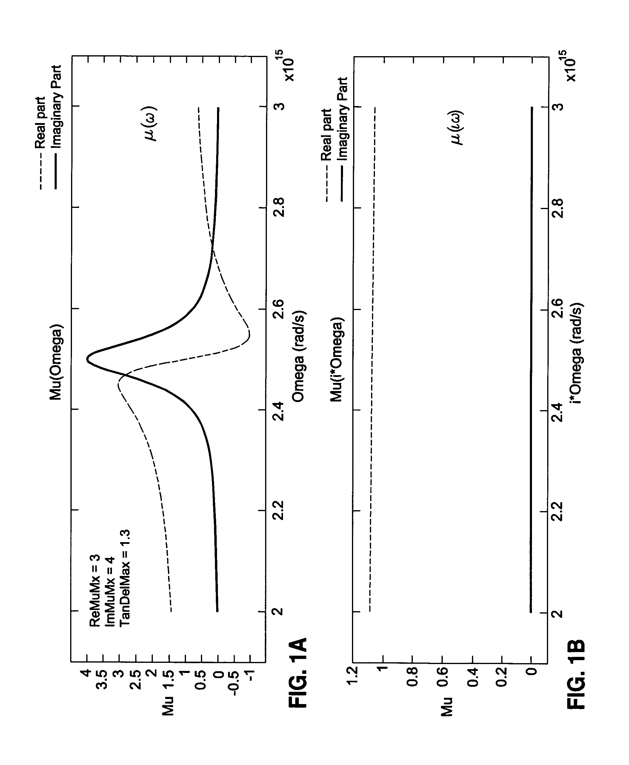
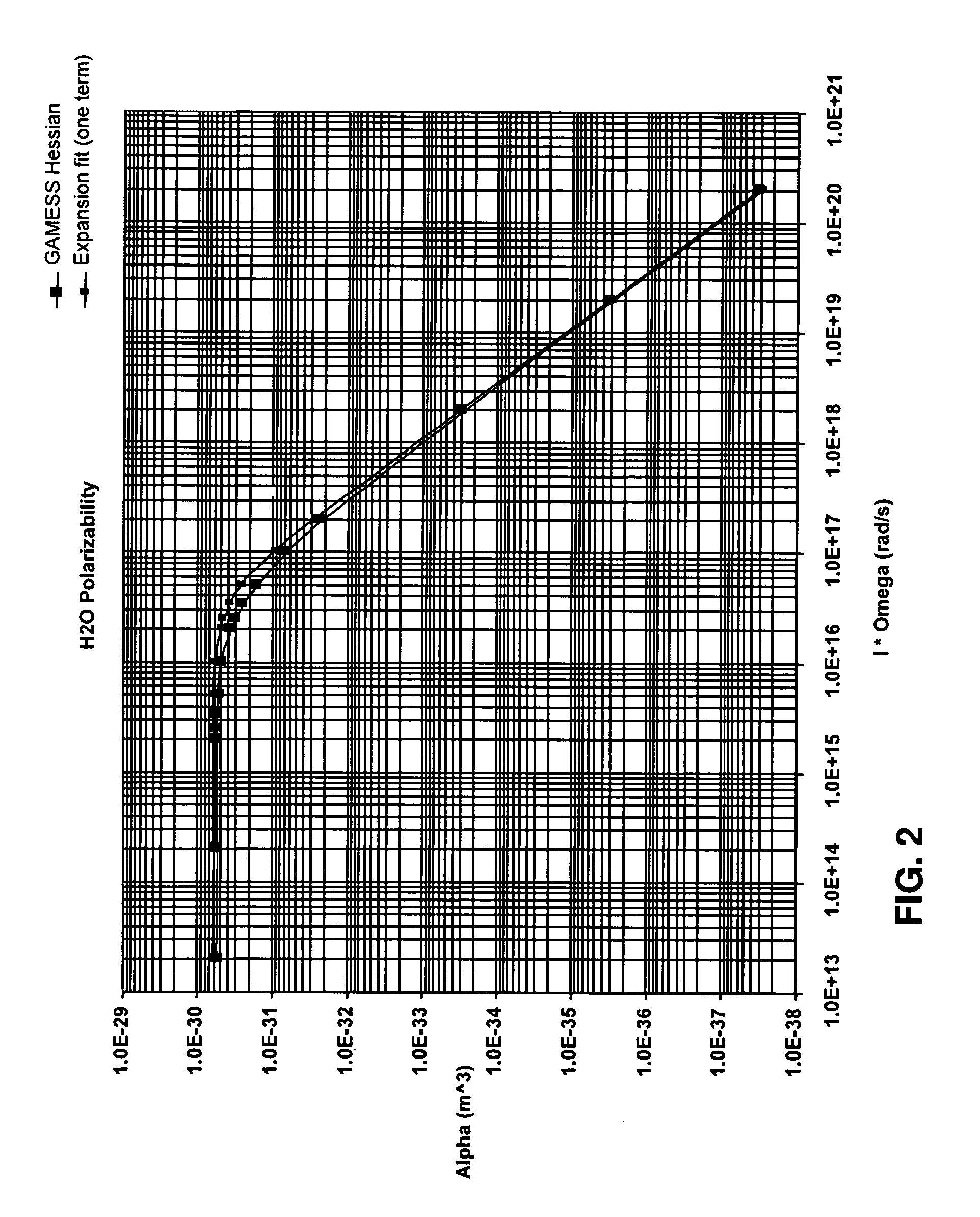
[0032]Embodiments as disclosed herein and as contemplated by the principles of the invention may preferably incorporate one or a combination of metamaterials preferably having high magnetic permeability and low electrical permittivity properties that are sufficient to generate a repulsive force between the metamaterial and the fluid flowing over the surface. As used in this disclosure, the term “van der Waals force” refers to and is typically character...


PUM

PropertyMeasurementUnit
diameteraaaaaaaaaa
frequenciesaaaaaaaaaa

Abstract

A metamaterial has a magnetic permeability response at frequencies sufficient to generate a repulsive force between a fluid and a surface to which the metamaterial may be applied. The metamaterial may be nanofabricated such that an absolute value of the magnetic permeability of the metamaterial is substantially greater than an absolute value of an electric permittivity of the metamaterial. The metamaterial may generate a repulsive force between the surface and the fluid moving relative to the surface and thereby reduce viscous drag of the fluid on the surface. A method of reducing the viscous drag of the fluid moving past the surface includes producing relative motion between the surface and the fluid and generating the repulsive force between the surface and the fluid.

Description

CROSS-REFERENCE TO RELATED APPLICATIONS[0001](Not Applicable)STATEMENT RE: FEDERALLY SPONSORED RESEARCH / DEVELOPMENT[0002](Not Applicable)FIELD[0003]The present disclosure relates generally to viscous drag and, more particularly, to a metamaterial configured to reduce viscous drag between a fluid and a surface.BACKGROUND[0004]A major contributor to the inefficiency of an object moving through a fluid is the friction drag or viscous drag that occurs at the boundary layer of the object. Friction drag or viscous drag tends to resist movement of the object through the fluid or movement of fluid over the object. For example, rotating machinery such as a turbine rotating in a fluid is subjected to viscous drag at the boundary layer of the object. In another example, a vehicle such as an aircraft moving through the air is subjected to friction drag or viscous drag at the boundary layer of the vehicle / air interface which tends to impede forward motion of the aircraft.[0005]Included in the pr...

Claims


Application Information

Patent Timeline
Patent Type & Authority Patents(United States)
IPC IPC(8): B64C3/36
CPCB64C23/00B64C23/005Y10T428/325Y02T50/166Y10T428/32B64C2230/12Y10T137/0391Y10T137/206Y02T50/10
Inventor PARAZZOLI, CLAUDIO G.TANIELIAN, MINAS H.GREEGOR, ROBERT B.
Owner THE BOEING CO
Learn More