Transport system

a technology of transport system and transport control, applied in the field of transport system, can solve the problems of large decrease in work transport efficiency, decrease in operating ratio, and decrease in production efficiency of the whole production facility, so as to reduce the load on the host computer, simplify the processing of transport control, and increase work transport efficiency

Active Publication Date: 2012-08-21
HIRATA & CO LTD
View PDF21 Cites 6 Cited by
  • Summary
  • Abstract
  • Description
  • Claims
  • Application Information

AI Technical Summary

Benefits of technology

[0007]It is an object of the present invention to improve the transport efficiency and reduce the load on the host computer.
[0009]In the transport system of the present invention, the transport means forms a plurality of transport paths from a transport source to a transport destination. Since a plurality of choices exist as the transport path of the work, the work transport efficiency can be increased. Transport control of the work is performed based on the transport path information stored in the storage medium provided on the work. It is therefore possible to reduce the load on the host computer as compared to a system which causes the host computer to unitarily manage work transport paths and execute control. Since the transport path information represents the transport direction of the work at a branch point in the transport path, processing of setting the work transport direction at the branch point is unnecessary, and the transport control processing can be simplified. Additionally, the system can flexibly cope with a change in the system layout.

Problems solved by technology

In a system having only one transport path from a transport source to a transport destination, if the transport equipment is partially faulty, or the work transport delays in the transport path, the work transport is completely tied up, resulting in a large decrease in the work transport efficiency.
This leads to a decrease in the operating ratio of, for example, a processing apparatus of the transport destination and a decrease in the production efficiency of the whole production facilities.
The load on the host computer becomes too heavy when simultaneously transporting many works.

Method used


Image

  • Transport system
  • Transport system
  • Transport system

Examples


Embodiment Construction

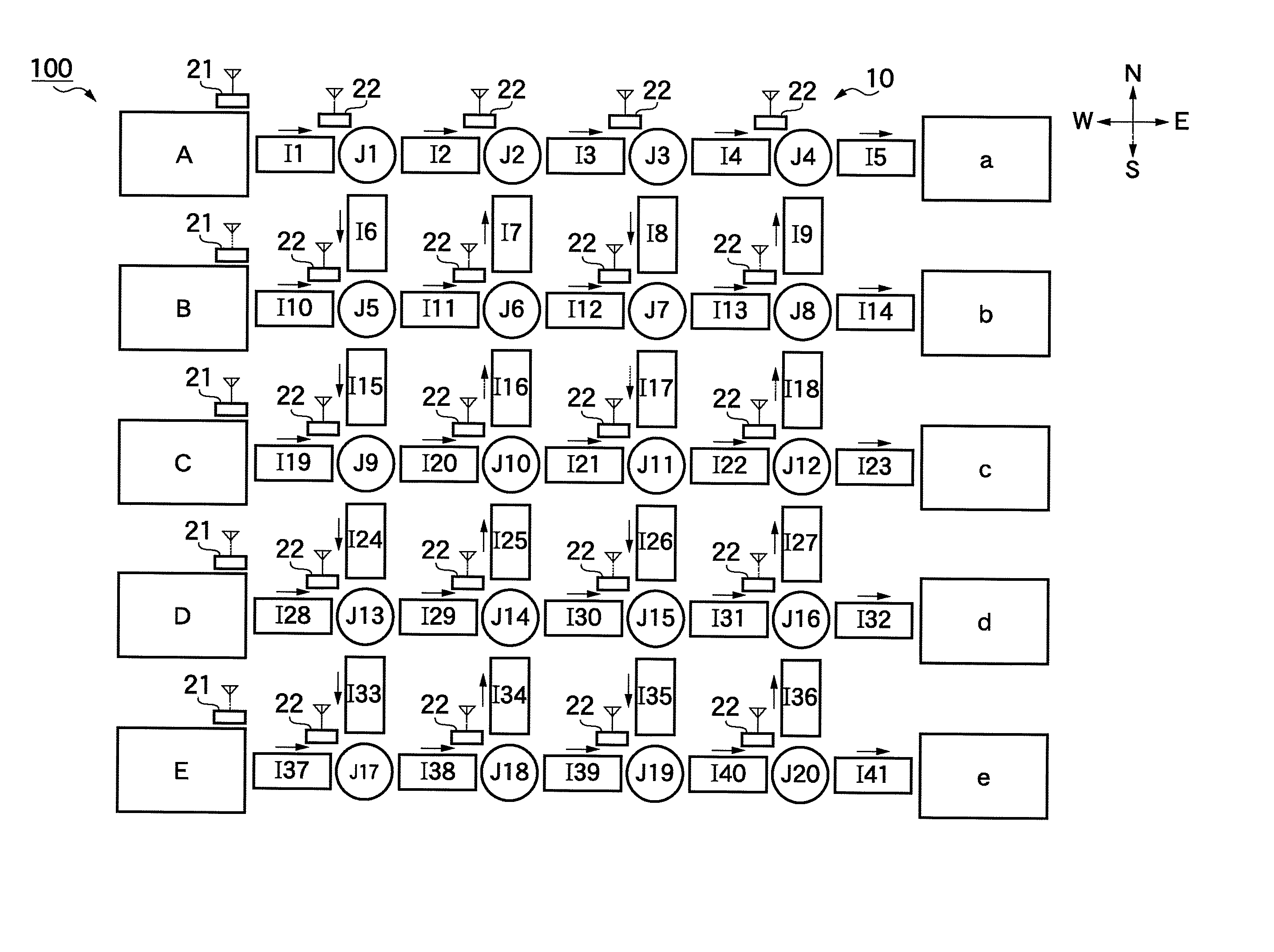
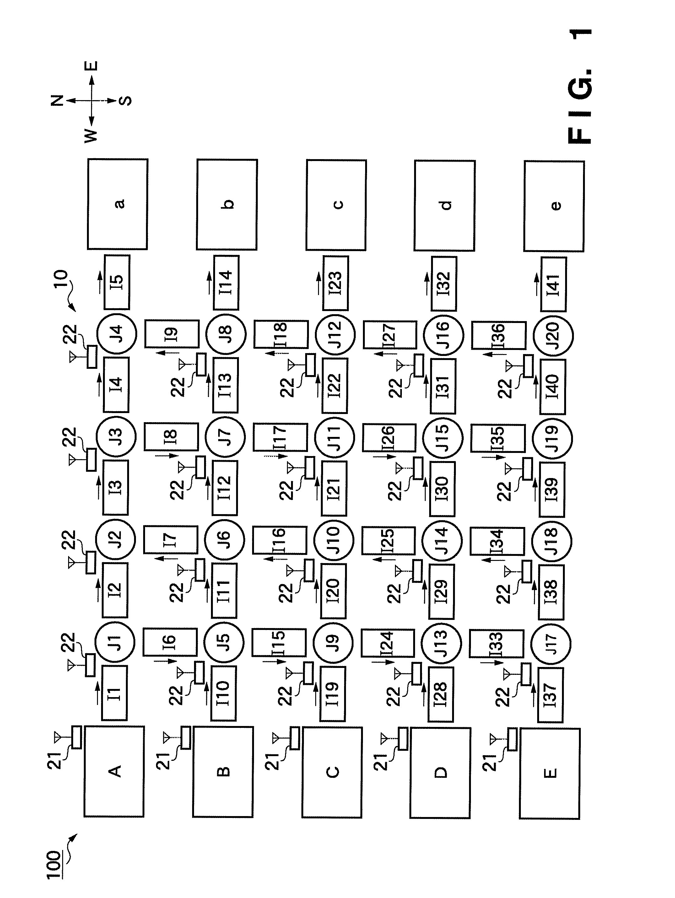
[0024]An embodiment of the present invention will now be described with reference to the accompanying drawings. FIG. 1 is a view showing the layout of a transport equipment 10 of a work transport system 100 according to an embodiment of the present invention. Referring to FIG. 1, each of apparatuses A to E is the transport source of a work serving as an object to be transported, and, for example, a processing apparatus for processing a work or a stocker for temporarily storing a work. Each of apparatuses a to e is the transport destination of a work serving as an object to be transported, and, for example, a processing apparatus for processing a work or a stocker for temporarily storing a work.

[0025]The transport equipment 10 includes a plurality of work transport units I1 to I41 and J1 to J20 (to be collectively referred to as work transport units I and J hereinafter). In FIG. 1, N, S, E, and W represent orientations in the factory where the transport equipment 10 is installed. The...


PUM


Abstract

A transport system of this disclosure includes a transporter for forming a plurality of transport paths from a transport source to a transport destination and transporting a work via a transport path selected from the plurality of transport paths, a controller for controlling the transport, and a reader for, when the work has arrived at a branch point in the transport path, reading out, from a storage medium, transport path information representing a transport direction of the work at the branch point in the transport path, the storage medium being provided on the work and storing the transport path information. The controller controls the transport to transport the work in the transport direction of the work at the branch point represented by the transport path information read out by the reader.

Description

TECHNICAL FIELD[0001]The present invention relates to a transport system for transporting an object to be transported such as a work.BACKGROUND ART[0002]In the production facilities of a semiconductor manufacturing system or the like, a substrate that is a work undergoes a plurality of kinds of processes. To do this, production facilities of this type must sequentially efficiently transport a work through a plurality of processing apparatuses.[0003]For example, Japanese Patent Laid-Open No. 9-255114 discloses a conventional transport system in which a host computer unitarily manages transport paths and executes transport control of each transport unit. Japanese Patent Laid-Open No. 7-287729 discloses a system which adds a barcode to each object to be inspected as an object to be transported to identify it. A conveyor reads the barcode and selectively transports each object to be inspected to an inspection apparatus or another conveyor. Japanese Patent Laid-Open No. 2000-117594 discl...

Claims


Application Information

Patent Timeline
Patent Type & Authority Patents(United States)
IPC IPC(8): B65G43/08
CPCG06Q10/047
Inventor OKUBO, HIROSHIKINOSHITA, HIROFUMIHORI, HIROSHIKANDABASHI, TSUGUMITSU
Owner HIRATA & CO LTD
Why Eureka
Try Eureka