Polishing disc for a tool for the fine machining of optically active surfaces particularly on spectacle lenses and method for its production

a technology of optical active surfaces and polishing discs, which is applied in the direction of gear teeth, gear teeth, gear head manufacturing apparatus, etc., can solve the problems of not achieving the desired effect, no significant polishing pressure can be exerted on the surface to be machined, and visible and therefore undesirable imprint of the polishing film edge, etc., to achieve rapid and accurate production of polishing discs, the effect of quick cutting operation

Active Publication Date: 2012-08-21
SATISLOH AG
View PDF12 Cites 8 Cited by
  • Summary
  • Abstract
  • Description
  • Claims
  • Application Information

AI Technical Summary

Benefits of technology

[0011]In both cases, therefore, in the polishing disc according to the invention, the intermediate layer is functionally split into a radial inner region of substantially constant axial thickness and an adjoining radial outer region which is assigned the task of preventing the edge of the polishing disc from being imprinted on the machined surface in the form of microstructures. Since the inner region has a substantially constant axial thickness, the elasticity or flexibility of the polishing disc does not vary over the radius thereof, unlike in the prior art according to U.S. Patent Publication 2007 / 0021036 As a result, given a suitable relative movement between the tool and the workpiece, advantageously a uniform polishing abrasion is achieved—Preston's hypothesis: the polishing abrasion is proportional to the product of the polishing pressure and the relative speed between the tool and the workpiece—so that the workpiece can be polished with a high constancy of topography, i.e. in a shape-retaining manner. Only in the edge region of the polishing disc, in which the radial outer region of the intermediate layer is located, does the polishing abrasion decrease due to a decreasing elastic support of the polishing agent carrier or due to the fact that the latter maintains space from the machined surface, and thus the possibility that the edge of the polishing disc can be imprinted on the machined surface is also reduced.
[0029]Furthermore, the cutting of the polishing agent carrier may take place by means of the punching tool and the counter-punch for punching out the intermediate layer, so that no separate tool has to be used for this and the cutting operation can take place quickly. Finally, the punching-out of the intermediate layer and the cutting of the polishing agent carrier may take place in a common operating step if these are separate raw materials. This also helps to achieve a rapid, accurate production of the polishing disc.

Problems solved by technology

This may lead to visible and therefore undesirable imprint of the polishing film edge, i.e. to very fine, scratch-like microstructures on the optically active surface of the spectacle lens.
Beyond the outer edge of the polishing film, it is no longer possible for any significant polishing pressure to be exerted on the surface to be machined.
However, tests carried out by the applicant have shown that this measure alone does not bring the desired success in all cases.
However, this prior art does not address the undesirable imprints of the polishing disc on the machined surface which are produced by the edge of the polishing film.

Method used


Image

  • Polishing disc for a tool for the fine machining of optically active surfaces particularly on spectacle lenses and method for its production
  • Polishing disc for a tool for the fine machining of optically active surfaces particularly on spectacle lenses and method for its production
  • Polishing disc for a tool for the fine machining of optically active surfaces particularly on spectacle lenses and method for its production

Examples


Embodiment Construction

OF EMBODIMENTS

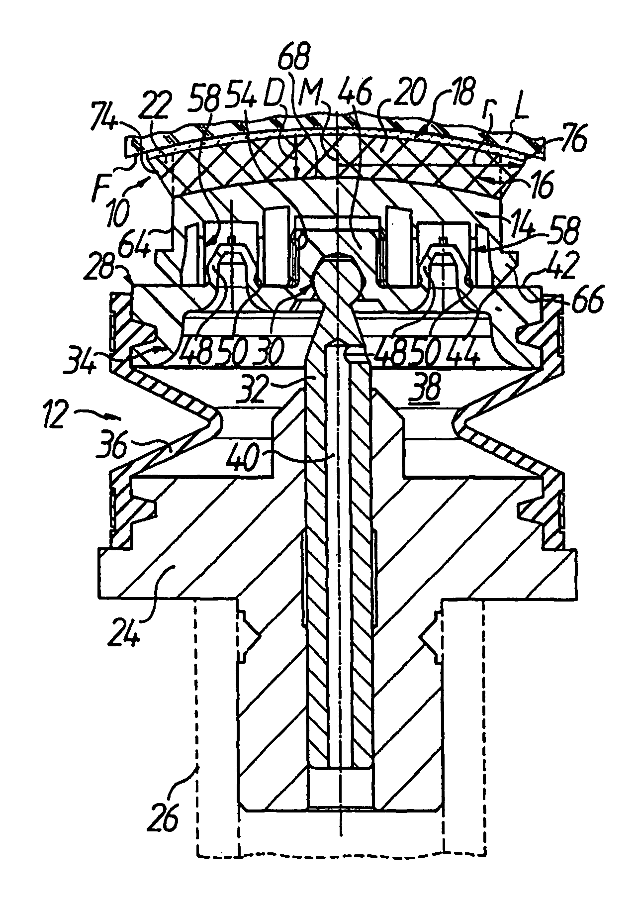
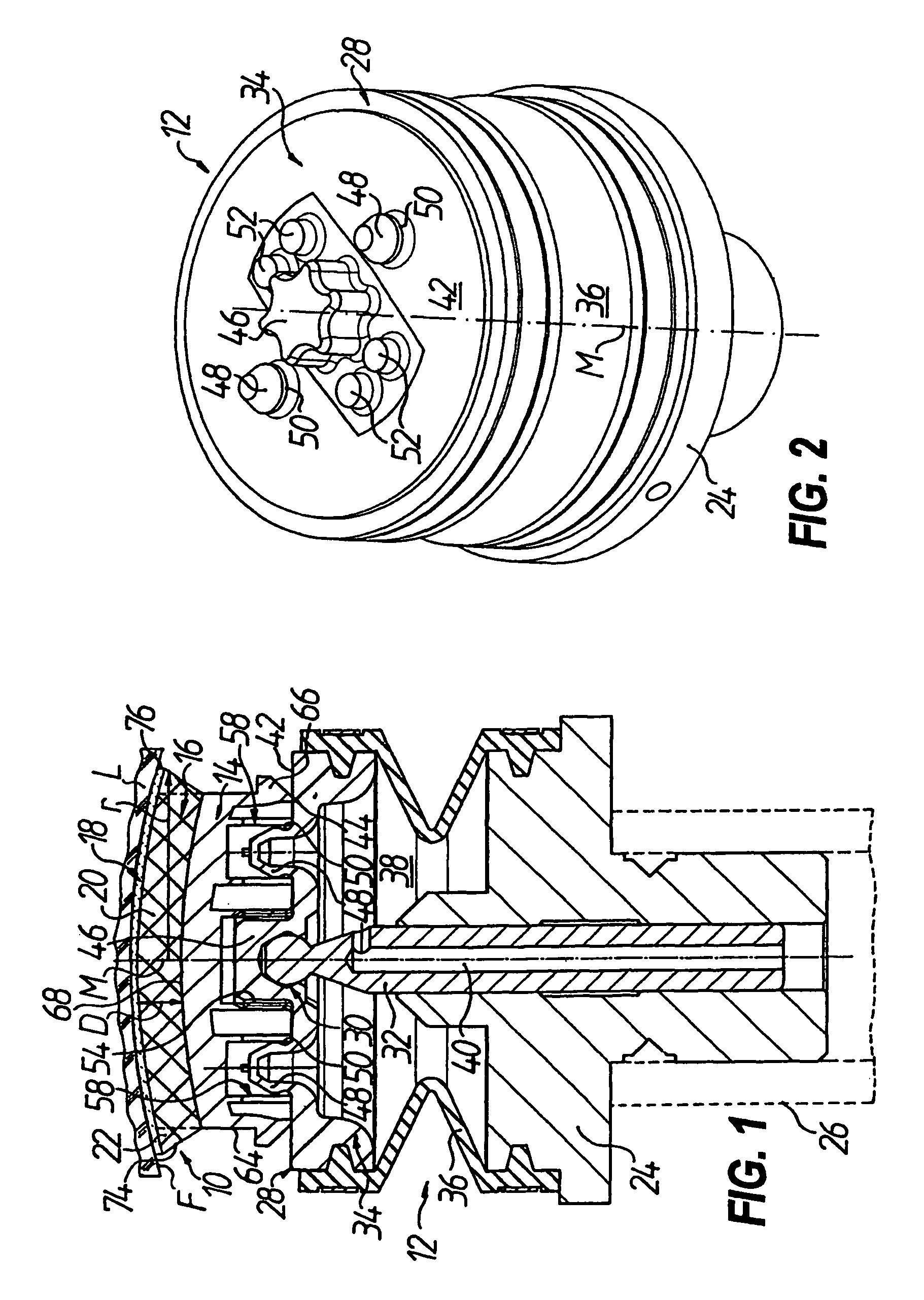
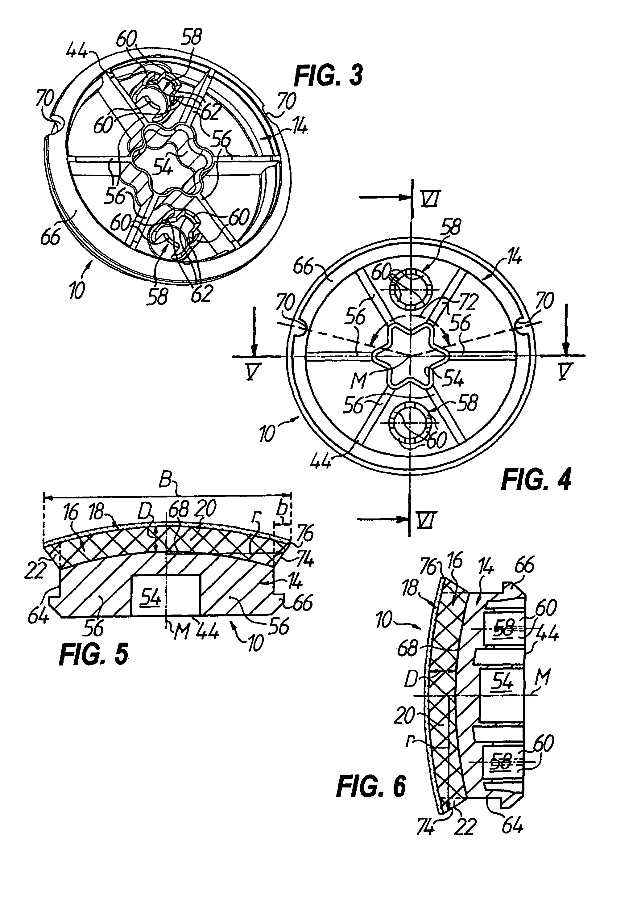
[0043]According to FIGS. 1, 5, 6 and 9 to 12, a polishing disc 10 for a tool 12 for the fine machining of optically active surfaces F particularly on spectacle lenses L comprises a main body 14 which has a center axis M and on which there is fixed an intermediate layer 16 which is softer than the main body 14 and on which a polishing agent carrier 18 rests. It is essential that the intermediate layer 16 has, with respect to the center axis M, a radial inner region 20 of substantially constant axial thickness D and an adjoining radial outer region 22 which, as will be described in greater detail below, is designed and fixed in a particular way so as to prevent the edge of the polishing disc 10 from being imprinted on the machined surface F of the spectacle lens L in the form of very fine, scratch-like microstructures. In FIGS. 1, 5, 6 and 9 to 12, dashed lines indicate the boundary between the radial inner region 20 and the radial outer region 22 of the intermediate lay...


PUM

PropertyMeasurementUnit
angleaaaaaaaaaa
thicknessaaaaaaaaaa
thicknessaaaaaaaaaa

Abstract

A polishing disc for a tool for the fine machining of optically active surfaces, particularly on spectacle lenses as workpieces, comprises a main body which has a center axis and on which there is fixed an intermediate layer which is softer than the main body and on which a polishing agent carrier rests. The intermediate layer has, with respect to the center axis, a radial inner region of substantially constant axial thickness and an adjoining radial outer region. The latter is formed or is fixed to the main body in a particular way so as to prevent the edge of the polishing disc from being imprinted on the machined surface of the workpiece in the form of very fine, scratch-like microstructures. Also proposed is a simple method which can be used to produce such a polishing disc.

Description

TECHNICAL FIELD[0001]The present invention relates to a polishing disc for a tool for the fine machining of optically active surfaces, which polishing disc comprises a main body that has a center axis and on which there is fixed an intermediate layer which is softer than the main body and on which a polishing agent carrier rests. Such polishing discs are used in large quantities in particular in the manufacture of prescription spectacle lenses. The invention also relates to a method for producing such a polishing disc.[0002]When the term “spectacle lenses” is used below by way of an example of workpieces with optically active surfaces, this is to be understood to mean not only spectacle lenses made from mineral glass but rather also spectacle lenses made from all other customary materials, such as polycarbonate, CR 39, Hi-Index, etc., that is to say plastic as well.PRIOR ART[0003]The machining of the optically active surfaces of spectacle lenses can roughly be split into two machini...

Claims


Application Information

Patent Timeline
Patent Type & Authority Patents(United States)
IPC IPC(8): B24B41/04B29C65/54B24B41/047
CPCB24B13/02B24D13/147B24D18/00Y10T156/1062Y10T156/1064
Inventor PHILIPPS, PETERURBAN, LOTHAR
Owner SATISLOH AG
Why Eureka
Try Eureka