
Apparatus, method, and system for improved switching methods for power adjustments in light sources

a technology for switching methods and light sources, applied in lighting apparatuses, light sources, instruments, etc., can solve the problems of general inflexibility of capacitance and limited effect of adjusting power to light sources in an electrical system using current available means of changing capacitance, and achieve significant flexibility in power level adjustmen

Inactive Publication Date: 2012-08-21
MUSCO
View PDF109 Cites 17 Cited by
  • Summary
  • Abstract
  • Description
  • Claims
  • Application Information

AI Technical Summary

Benefits of technology

The present invention provides an improved method of adjusting power to light sources in an electrical system by using a combinational approach to changing capacitance. This allows for flexibility in managing energy consumption, controlling light output, and compensating for light losses. The invention also includes a system that is flexible, space and component efficient, robust, accurate, and economical. The method and system can be used in a variety of applications, such as large area outdoor sports lighting systems. The invention also allows for remote control and integration of improved switching methods and combinational capacitance in a wide area or sports lighting system to provide a flexible method of power control for the purposes of energy conservation, preserving the quantity of light output, and maintaining constant light output.

Problems solved by technology

The effectiveness of adjusting power to light sources in an electrical system using currently available means of changing capacitance tends to be limited by the physical space required to provide a plurality of capacitors with traditional switching mechanisms, and the general inflexibility of capacitance changing systems.

Method used


Image

  • Apparatus, method, and system for improved switching methods for power adjustments in light sources
  • Apparatus, method, and system for improved switching methods for power adjustments in light sources
  • Apparatus, method, and system for improved switching methods for power adjustments in light sources

Examples


embodiment 1

C. Exemplary Method and Apparatus Embodiment 1

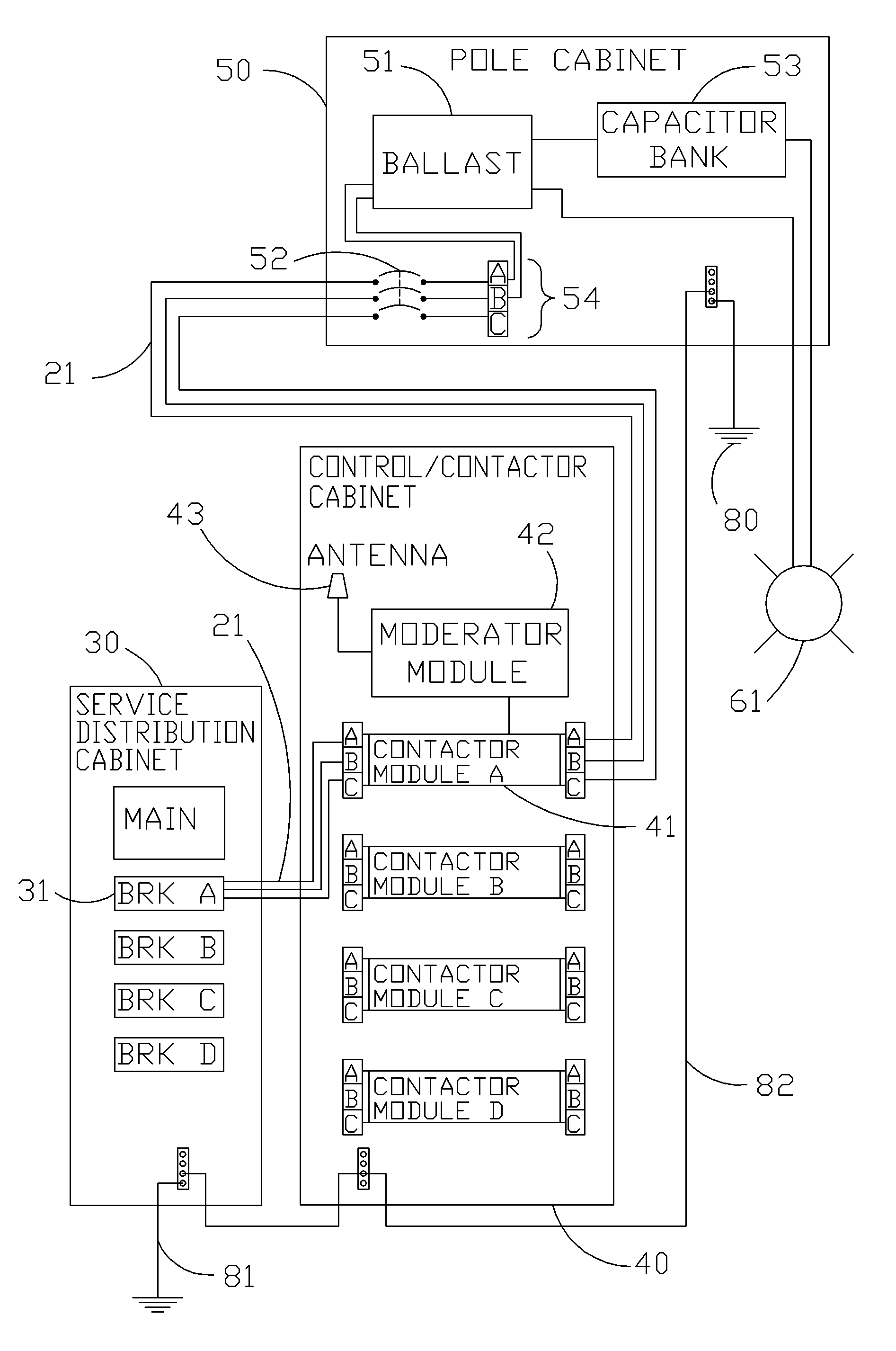
[0100]A more specific exemplary embodiment, utilizing aspects of the generalized example described above, will now be described. An electrical system operating a capacitor bank utilizing a plurality of capacitors as illustrated in FIG. 9A, to achieve the capacitance values illustrated in Table 2, is enabled with a solenoid switching method as illustrated in FIGS. 9B and 10A-C; and operated by a circuit control as illustrated in FIGS. 11A and 11B.

[0101]With respect to Table 2, Capacitor 1 is a base capacitor that typically remains in the circuit; note Capacitor 1 (as is illustrated by C1, FIG. 9A) is shown integral to the light source circuit. Capacitor 2 (as is illustrated by C2, FIG. 9A) is of a relatively large capacitance and may generally be switched out via solenoid switch 120, FIG. 9A (e.g. when dimming the circuit for purposes of energy conservation or otherwise). Capacitors 3-6 (as are illustrated by C3-C6, FIG. 9A) are of relati...

embodiment 2

D. Exemplary Method and Apparatus Embodiment 2

[0120]An alternative embodiment of the invention envisions an electrical system operating a capacitor bank utilizing a plurality of capacitors as illustrated in FIG. 9A, to achieve the capacitance values illustrated in Table 2, enabled with a solenoid switching method as illustrated in FIGS. 9B and 10A-C; and operated by a circuit control is illustrated in FIGS. 12A and 12B. In this alternative embodiment the electrical system utilizing the improved switching methods and combinational capacitance as described herein does not have remote control capabilities. With respect to FIG. 12A, operation of the light source 61, FIG. 12B, may be enabled by the following.[0121]1. Upon installation of the electrical system (see FIG. 12B), the controller 56 is loaded with multiple operating profiles via the communication connection.[0122]a. For example, an operating profile utilizes known depreciation data for the light source 61, FIG. 12B, and adjusts...

embodiment 3

E. Exemplary Method and Apparatus Embodiment 3

[0129]An alternative embodiment of the invention envisions an electrical system operating a capacitor bank utilizing a plurality of capacitors as illustrated in FIG. 13A enabled with a cam / solenoid switching method as illustrated in FIGS. 13B, 14A and 14B; and operated by a circuit control as illustrated in FIG. 11A / 11B or 12A / 12B. In this alternative embodiment the motor in the cam / motor system used in current art is replaced with a solenoid.

[0130]As may be seen from FIG. 13A, the circuit control 58 / 59 operates a pulsed solenoid 240 via solenoid actuation signal 123; the circuit control 58 / 59, solenoid 240, and actuation signal 123 are as in Exemplary Method and Apparatus Embodiments 1 and 2. The solenoid actuates a mechanical escapement 280, FIG. 14A, which, in turn, operates the armature 230, FIG. 14A and associated cams 220, FIG. 14A, to provide the rotary switching function 241 to each switching mechanism 130; as may be seen from FI...


PUM


Abstract

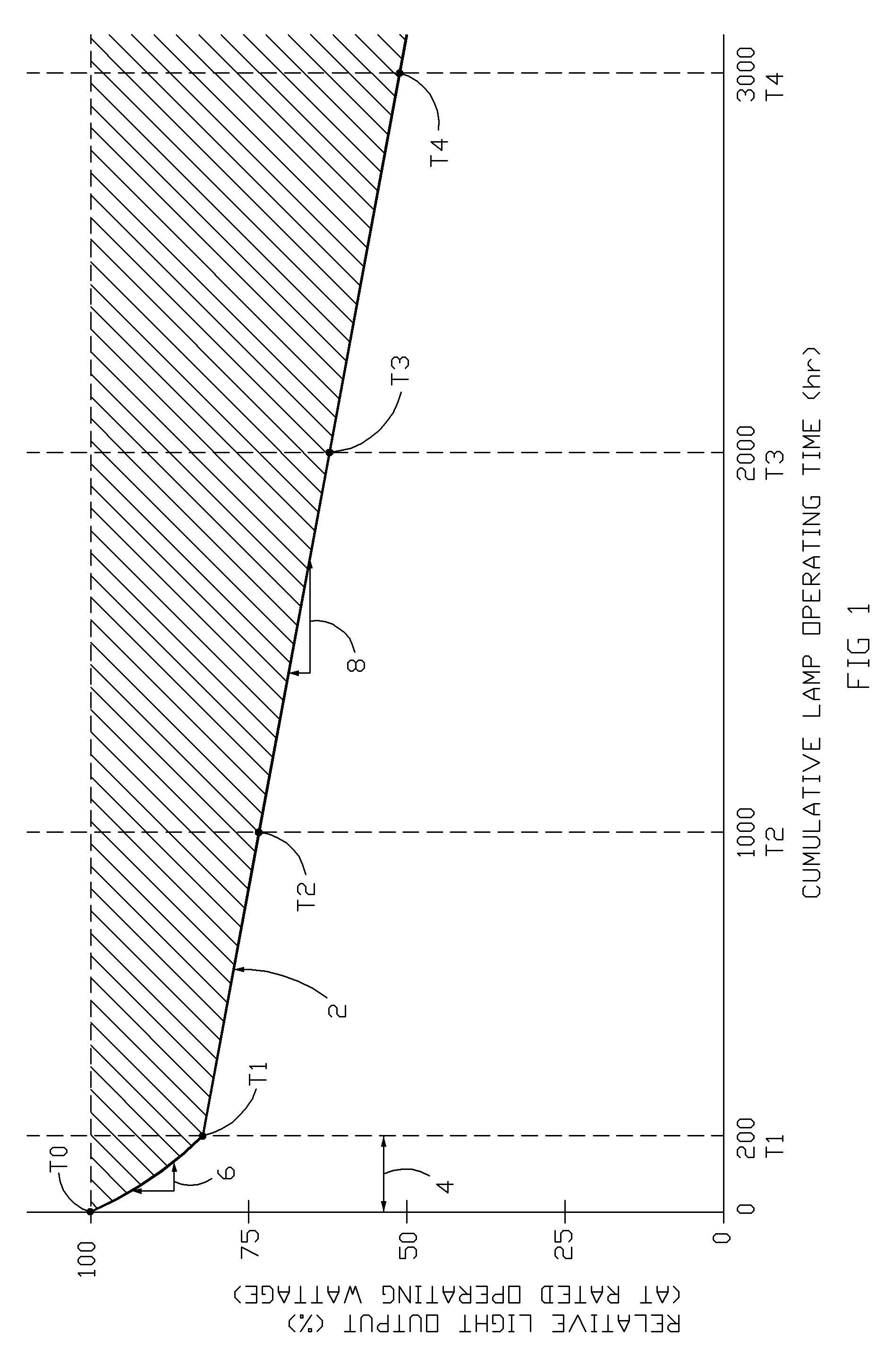
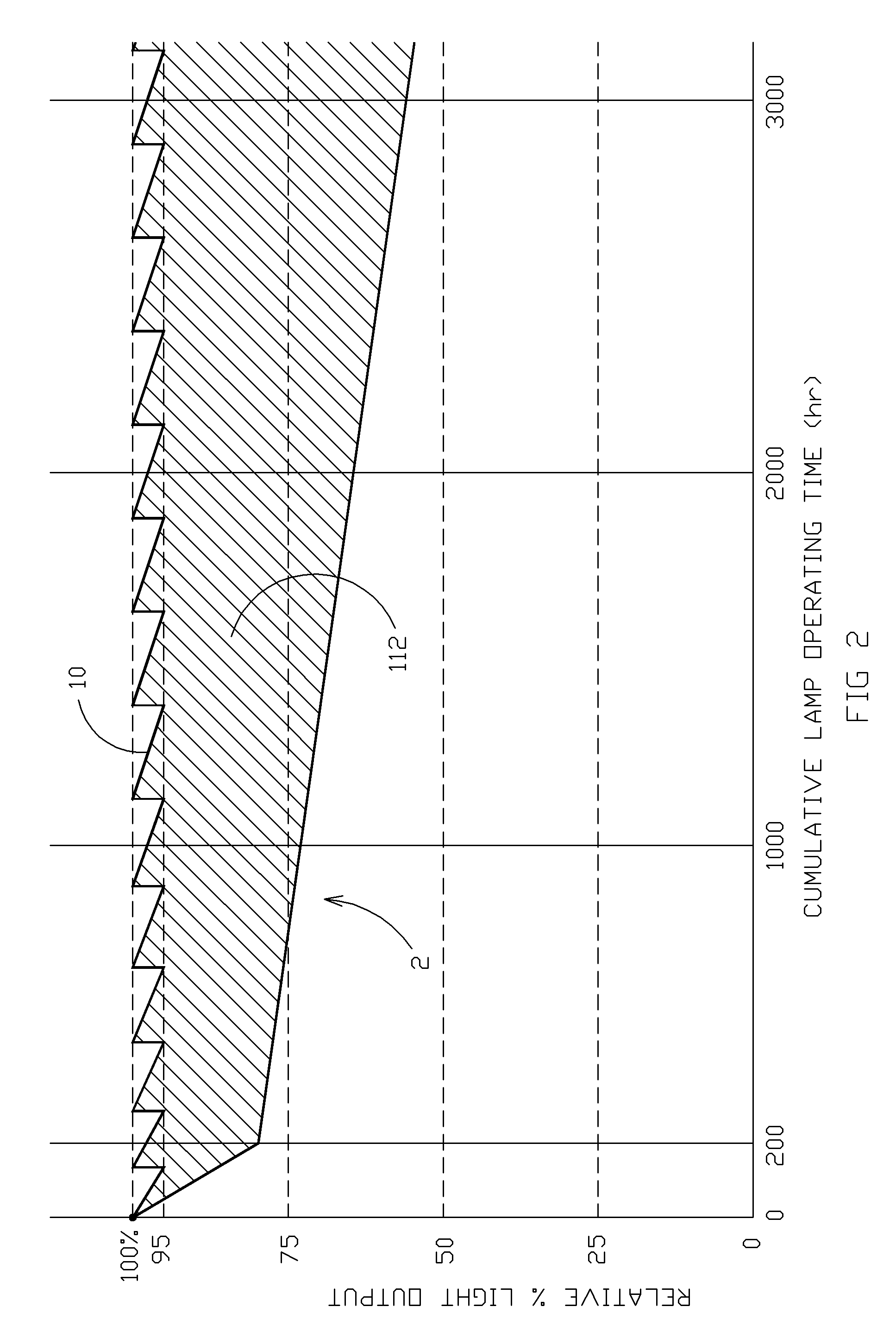
An apparatus, method, and system for switch control of power to light sources, particularly high power consumption light sources that may experience lumen depreciation, such that the power level to a light source may be increased or decreased as desired. Methods of switching utilizing robust mechanical components such as solenoids, coupled with accurate and rapid electronic control components such as microprocessors, may be combined with a combinational approach to capacitance changes to comprise a flexible method of power control to a light source or plurality of light sources. Power to a light source may be adjusted such that the amount of energy consumed and the quantity of light output may be adjusted, compensation may be made for lumen depreciation and other losses that occur during operational life of the light source, to maintain constant or near-constant light output, or otherwise.

Description

CROSS-REFERENCE TO RELATED APPLICATIONS[0001]This application claims priority under 35 U.S.C. §119 to provisional U.S. application Ser. No. 61 / 201,066, filed Dec. 5, 2008, hereby incorporated by reference in its entirety.I. BACKGROUND OF INVENTION[0002]A. Field of Invention[0003]The present invention relates to switch control of power to light sources, particularly high power consumption light sources, such that the power level to a light source may be increased or decreased as desired. Improved methods of switch control may be applicable to a variety of components within an electrical system, and may be combined with combinational capacitance to comprise a flexible method of power control to a light source. Power to a light source may be adjusted such that the amount of energy consumed and the quantity of light output may be adjusted, compensation may be made for lumen depreciation and other losses that occur during operational life of the light source, constant or near-constant li...

Claims


Application Information

Patent Timeline
Patent Type & Authority Patents(United States)
IPC IPC(8): H05B37/02
CPCH05B41/40
Inventor GORDIN, MYRONBOYLE, TIMOTHY J.KUBBE, GREGORY N.GROMOTKA, GABRIEL P.
Owner MUSCO
Learn More