Control unit and control method for torque-demand-type internal combustion engine

a technology of internal combustion engine and control unit, which is applied in the direction of electric control, ignition automatic control, machines/engines, etc., can solve the problems of difficult to achieve the required torque, shock and vibration, etc., and achieve the effect of increasing the torque, increasing the intake efficiency of the internal combustion engine, and increasing the torque generated by the internal combustion engin

Inactive Publication Date: 2012-08-28
TOYOTA JIDOSHA KK
View PDF29 Cites 5 Cited by
  • Summary
  • Abstract
  • Description
  • Claims
  • Application Information

AI Technical Summary

Benefits of technology

[0015]The invention provides a control unit and control method for a torque-demand-type internal combustion engine suitable for a fuel-supply cutoff control, which minimizes a shock that is likely to be caused when a fuel-supply cutoff is started and a fuel supply is restarted.

Problems solved by technology

This may cause a shock and vibration when the fuel-supply cutoff control is started.
As a result, it is sometimes difficult to achieve the required torque.

Method used


Image

  • Control unit and control method for torque-demand-type internal combustion engine
  • Control unit and control method for torque-demand-type internal combustion engine
  • Control unit and control method for torque-demand-type internal combustion engine

Examples


first modified example

[0116]Hereafter, a first modified example of the embodiment of the invention will be described with reference to FIG. 8. The first modified example has the following features in addition to the features of the above-described embodiment.

[0117]When the accelerator pedal is released, the torque required by the driver is decreased to the base torque. That is, the torque required by the driver is not allowed to fall below the base torque. As shown in FIG. 8; the torque required by the driver matches the base torque.

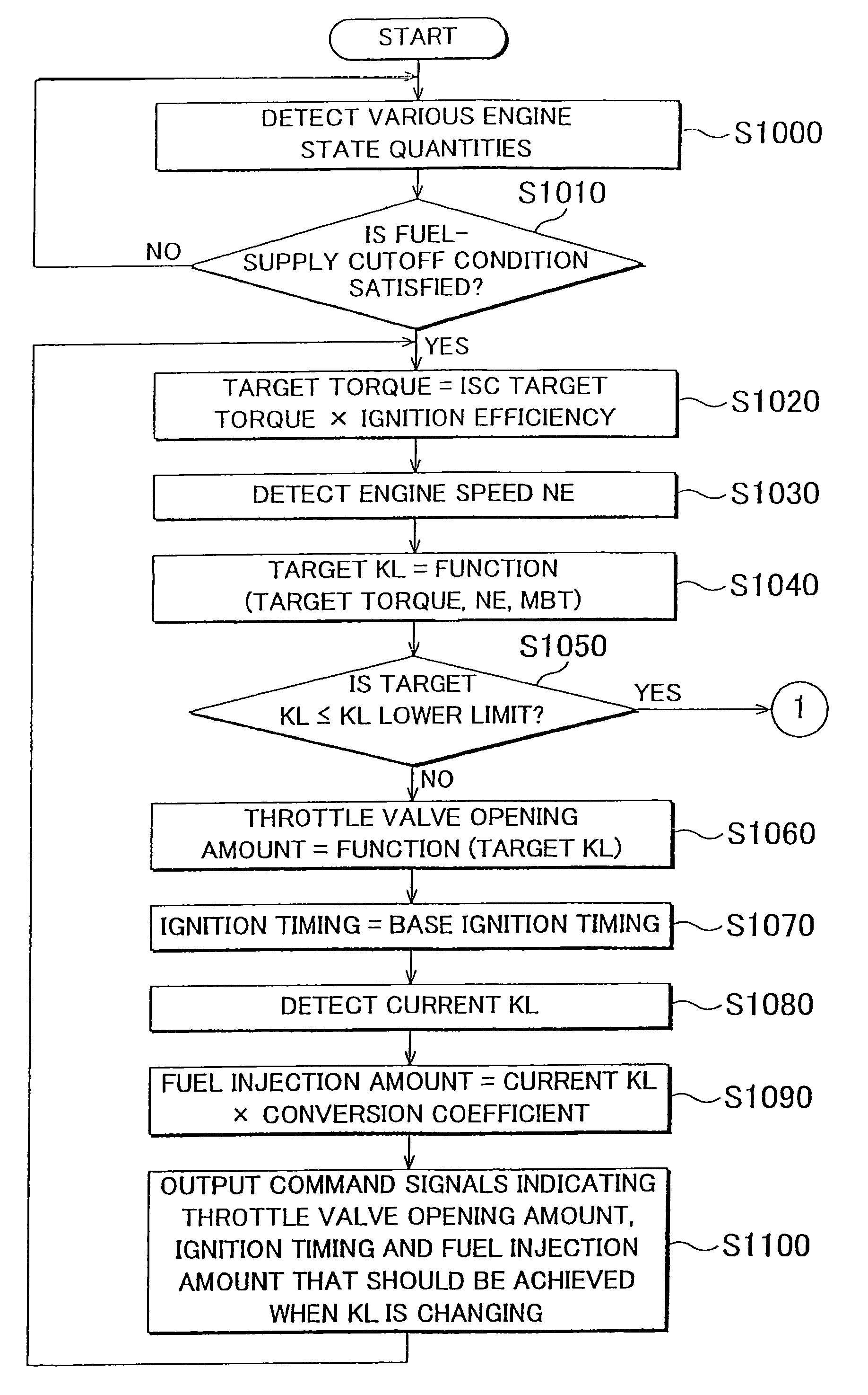
[0118]The generable limit torque (lower limit torque) is set to the torque that is generated at the ignition timing at which the intake efficiency is decreased by the largest amount within a range, in which the fuel injected from the injector 126 is ignited, at the engine speed NE corresponding to the base torque.

[0119]When the condition that the torque required by the driver is lower than the generable limit torque is satisfied, the fuel supply is cut off. When the condition...

second modified example

[0121]Hereafter, a second modified example of the embodiment of the invention will be described with reference to FIG. 9. The second modified example has the following features in addition to the features of the embodiment of the invention described above.

[0122]In the second modified example, the base torque is set to the highest value from among a) the torque determined based on the target idling torque (ISC target torque), b) the torque determined based on the limit amount of fuel injected from the injector 126 (which is the minimum amount of fuel injected from the injector 126 and which is the lower limit of a range in which the linear relationship between the fuel injection duration and the fuel injection amount is established), and c) the torque determined by multiplying the limit of a negative value in an intake pipe (due to consumption of, for example, engine oil) by the most retarded angle (retardation limit).

[0123]According to the second modified example, the effects produc...


PUM


Abstract

When a fuel-supply cutoff condition is satisfied, an ECU executes a program including: calculating the target torque; detecting the engine speed NE; calculating the target KL based on the target torque, NE and MBT; controlling an engine using the throttle valve opening amount based on the target KL, the base fuel ignition timing, and the fuel injection amount based on the current KL until the target KL becomes equal to or lower than the KL lower limit; controlling the engine using the throttle valve opening amount based on the KL lower limit, NE, the target ignition timing calculated based on the current KL and the target torque, and the fuel injection amount based on the current KL when the target KL reaches the KL lower limit; and actually starting a fuel-supply cutoff when the target ignition timing reaches the retardation limit timing.

Description

BACKGROUND OF THE INVENTION[0001]1. Field of the Invention[0002]The invention relates generally to a control unit and control method for an internal combustion engine, which executes a fuel-supply cutoff control, and, more specifically to a fuel-supply cutoff control executed over an internal combustion engine of which the operating state is adjusted to control the output torque (hereinafter, this type of internal combustion engine will be referred to as “torque-demand-type internal combustion engine”).[0003]2. Description of the Related Art[0004]In many types of vehicles provided with an internal combustion engine (hereinafter, referred to as “engine” where appropriate), a so-called fuel-supply cutoff control, that is, a control for cutting off the fuel supply, is executed while the vehicle is decelerating in order to enhance the fuel efficiency. The fuel-supply cutoff control is executed in order to enhance the fuel efficiency by minimizing the amount of fuel that is supplied to t...

Claims


Application Information

Patent Timeline
Patent Type & Authority Patents(United States)
IPC IPC(8): F02P5/15F02M3/00
CPCF02D37/02F02D41/123F02D41/126F02P5/1504F02D2200/0411F02D2250/21Y02T10/46Y02T10/40
Inventor ITO, MASAHIRO
Owner TOYOTA JIDOSHA KK
Why Eureka
Try Eureka