
Method and apparatus for transferring signal data

a signal data and signal technology, applied in the field of information technology, can solve the problems of increasing the complexity of the receiving system, affecting the accuracy of received information, so as to achieve the effect of increasing capacity and improving accuracy

Active Publication Date: 2012-08-28
ABB (SCHWEIZ) AG
View PDF41 Cites 2 Cited by
  • Summary
  • Abstract
  • Description
  • Claims
  • Application Information

AI Technical Summary

Benefits of technology

[0010]The invention and its preferred embodiments provide the advantages, for instance, that the sender may input a new sample at any time and using any sampling frequency, and the receiver may read the signal value at any time either randomly or regularly. The data transfer rate and delay of the physical link may be as required on the condition, however, that the accuracy of the received information improves as the capacity increases.

Problems solved by technology

All data transfer links cause delays in data transfer.
In addition, the extrapolation increases the complexity of the receiving system.
A problem with the above methods and systems is that the sample values are outdated and, therefore, erroneous by the time they arrive at the PID controller.
In addition to this, when using extrapolation, the properties of the data transfer link need to be known—which is not always possible—and it is difficult to compensate for the effect of jitter.

Method used


Image

  • Method and apparatus for transferring signal data
  • Method and apparatus for transferring signal data
  • Method and apparatus for transferring signal data

Examples


Embodiment Construction

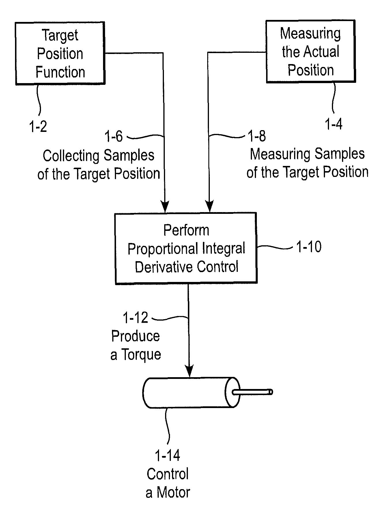
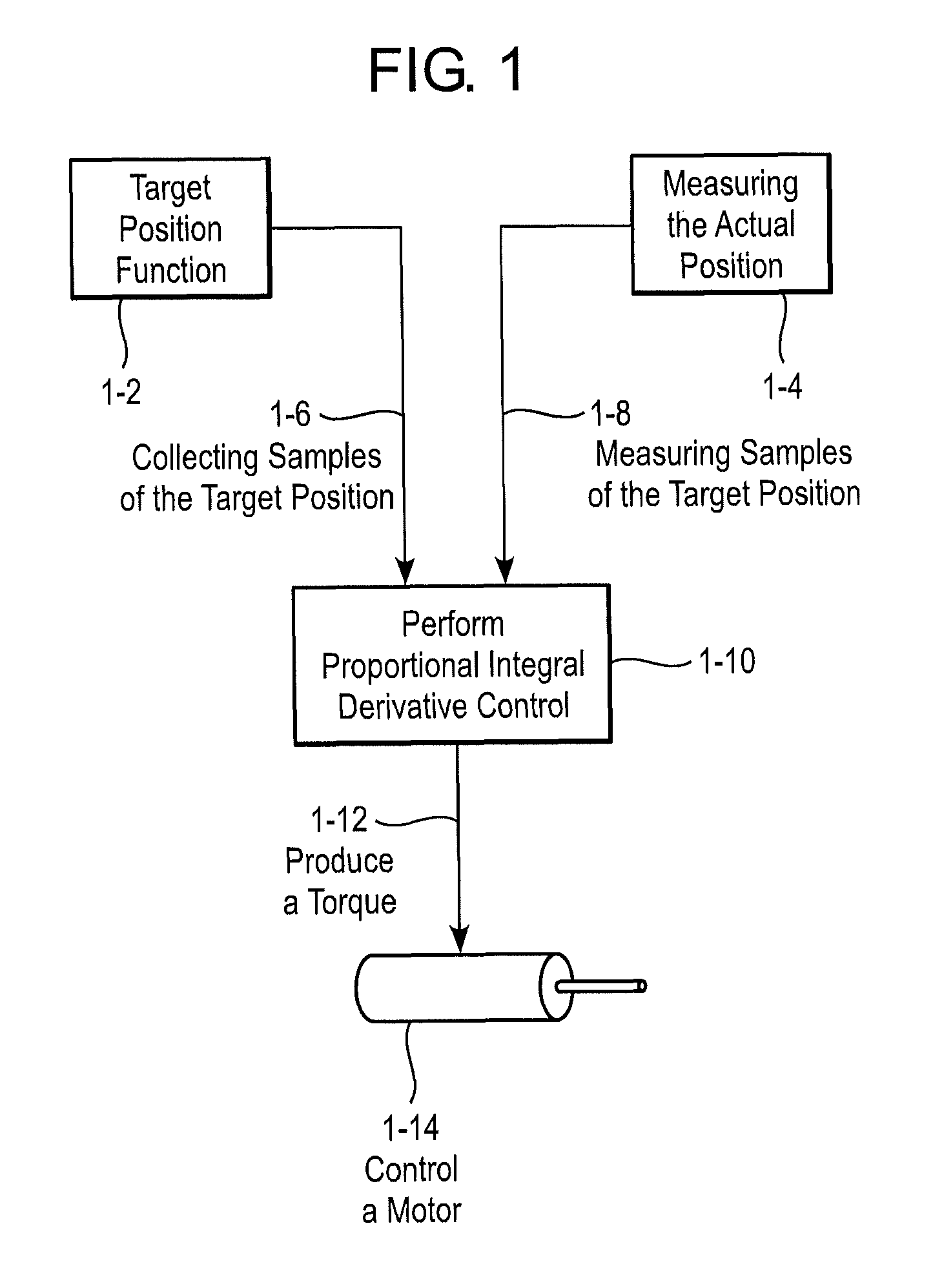
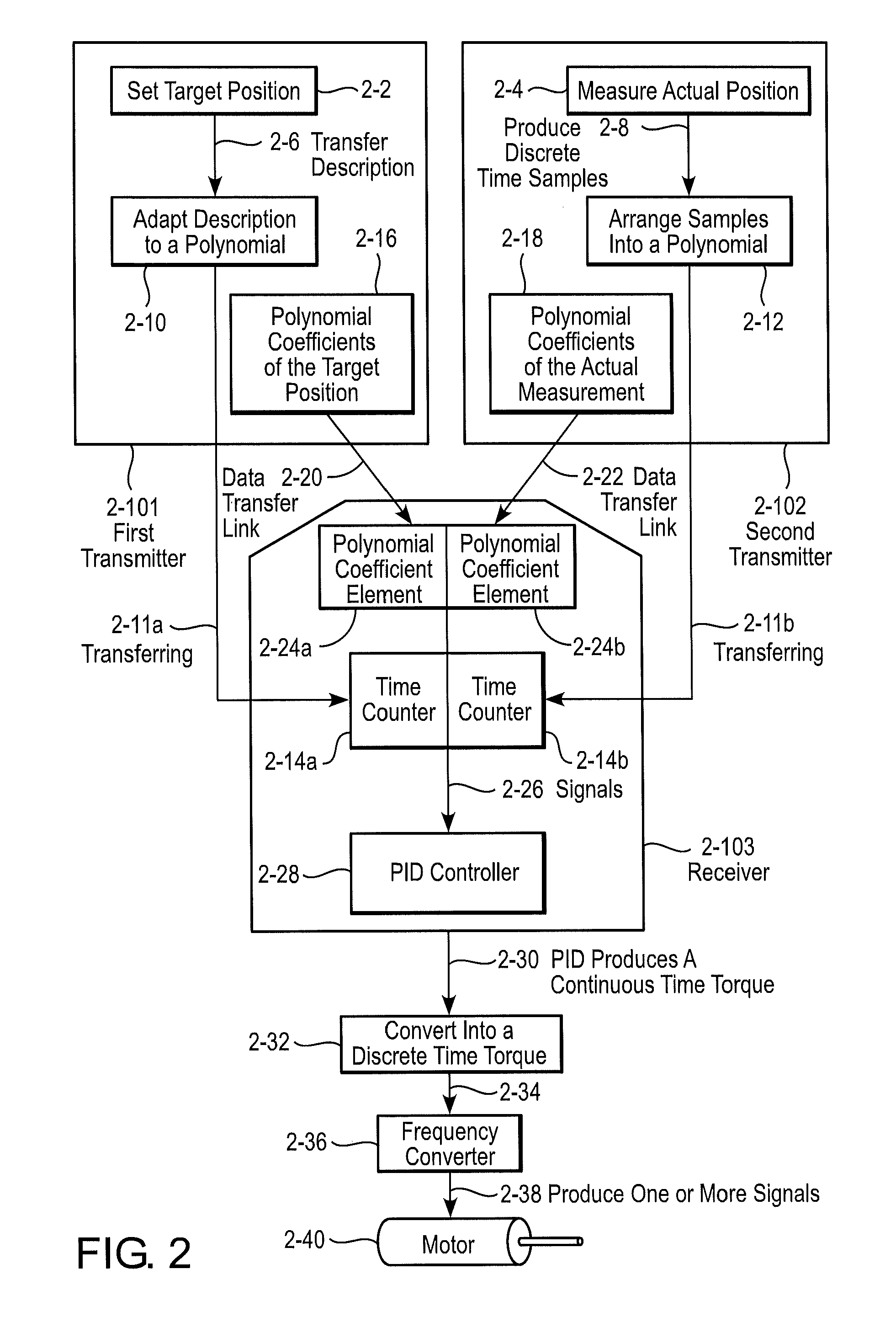
[0017]FIG. 2 shows the implementation of position control according to the invention and its preferred embodiments. The adjustable, guidable, or controllable quantity may be any quantity, and is not restricted to position control. In addition, there may be one or more adjustable quantities. A variable according to which the quantity is described may be time, another variable, or a combination of variables. In FIG. 2, the target position may be set 2-2 by information engineering and described continuously or discretely as function of time. The description may be a description of the position of three different time instants, for example. The description may be transferred 2-6 to an element to adapt the description to a polynomial 2-10. The arrangement may be done using equation calculation or matrix calculation, i.e., matrix calculation, for example, may be used in defining the coefficients of the polynomial. For instance, from a group of three equations, the unknown factors may be s...


PUM


Abstract

The invention relates to a method and device for transferring signal data from a sender to one or more receivers. The invention includes receiving a quantity as a function of time, arranging the quantity into a first polynomial to obtain values for polynomial coefficients of a first continuous signal, and transferring the values of the polynomial coefficients of the first continuous signal via a first data transfer link to one or more receivers.

Description

BACKGROUND OF THE INVENTION[0001]The invention relates to information technology and especially to the compensation and minimization of delays in the data transmission of information technology.PRIOR ART[0002]In automation systems, data is usually transferred by measuring an analogue quantity, such as position information, speed, voltage or current, from a circuit board A, sampling a measuring signal at certain sampling time instants, and quantizing and coding the signal into numerical values in digital format. After this, the digital signal is transferred one sample at a time by using a digital parallel or series link to a circuit board B, where the signal is used for different purposes. All data transfer links cause delays in data transfer. In some links, the delay also varies randomly or pseudo-randomly. If the samples are examined at the receiving end without information on the sampling time, the signal has temporal uncertainty.[0003]The uncertainty and delay described above is ...

Claims


Application Information

Patent Timeline
Patent Type & Authority Patents(United States)
IPC IPC(8): H04Q9/00G05D1/02
CPCG01S5/0018G06F17/17G05B11/42
Inventor NIEMI, MIKA
Owner ABB (SCHWEIZ) AG
Learn More