Wideband wide scan antenna matching structure using electrically floating plates

a wide-band, antenna technology, applied in the field of antennas, can solve the problems of metal blocks wasting both space or volume and height of individual elements, and achieve the effect of less volum

Active Publication Date: 2012-08-28
NORTHROP GRUMMAN SYST CORP
View PDF9 Cites 10 Cited by
  • Summary
  • Abstract
  • Description
  • Claims
  • Application Information

AI Technical Summary

Benefits of technology

[0012]The plates element or layer of the present invention utilizes the same stepped impedance matching approach as a traditional stepped notch, but does so in a much more efficient manner. FIGS. 3 and 4 shows how the stepped impedance transforms are rotated and folded within the present plates element. Each impedance transform is implemented by properly spacing and sizing the planar metal plates. This rotation, folding, sizing and spacing allows the present plates element to realize the desired taper and meet the bandwidth requirements in much less volume.

Problems solved by technology

Such metal blocks wasted both space or volume and height of the individual elements.

Method used


Image

  • Wideband wide scan antenna matching structure using electrically floating plates
  • Wideband wide scan antenna matching structure using electrically floating plates
  • Wideband wide scan antenna matching structure using electrically floating plates

Examples


Embodiment Construction

[0024]So that the manner in which the above recited features, advantages and objects of the present invention are attained can be understood in detail, more particular description of the invention, briefly summarized above, may be had by reference to the embodiment thereof that is illustrated in the appended drawings. In all the drawings, identical numbers represent the same elements.

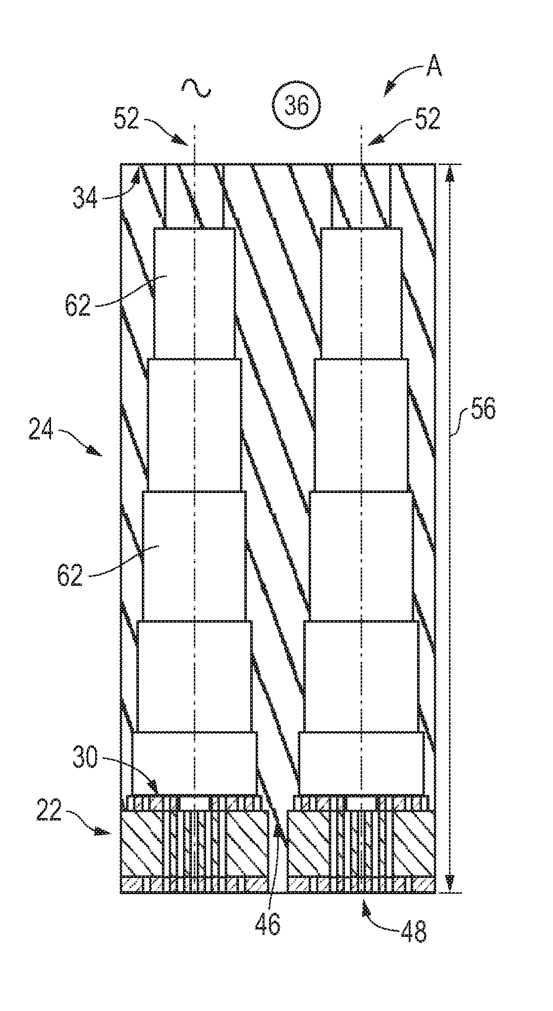
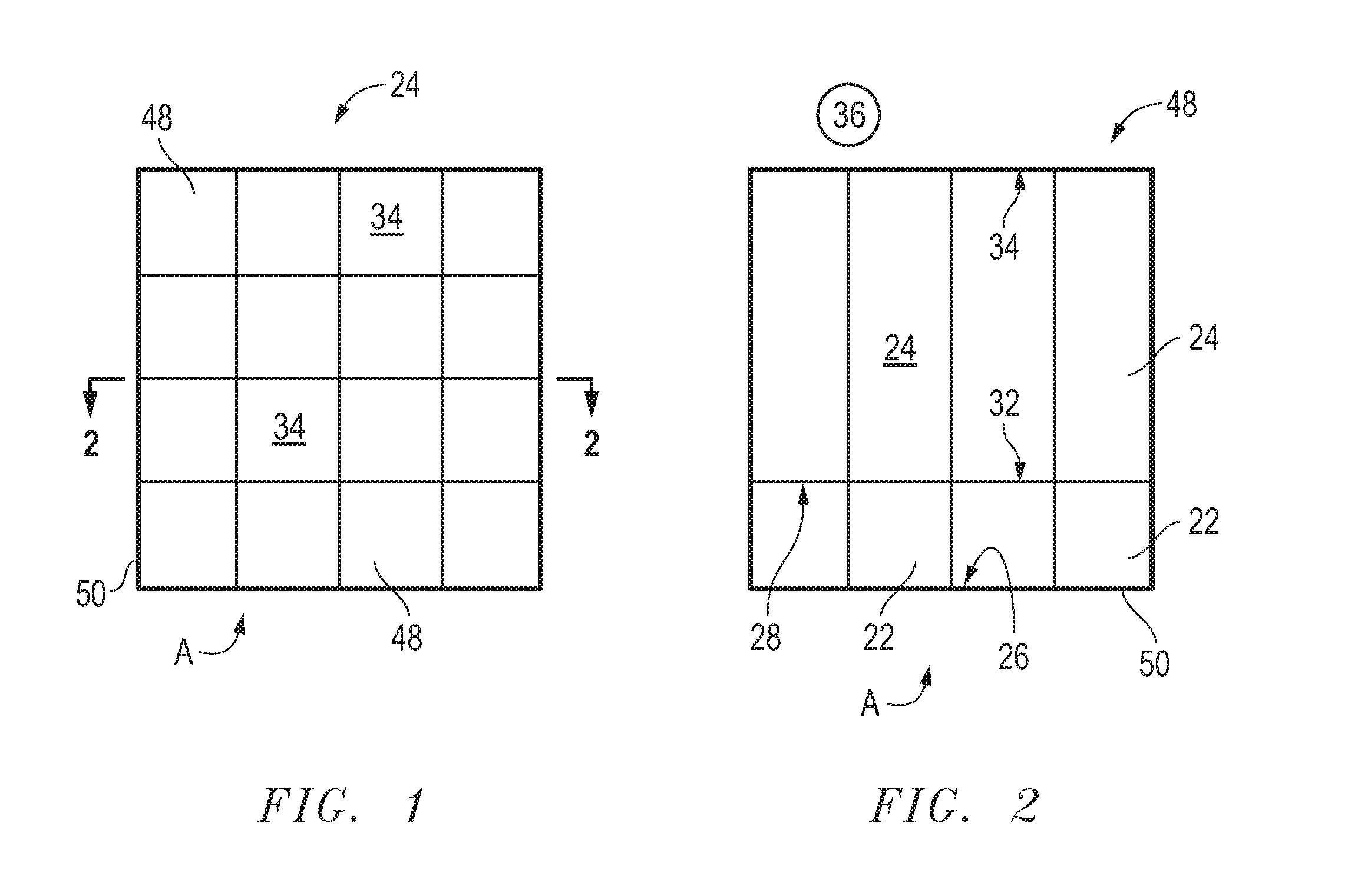
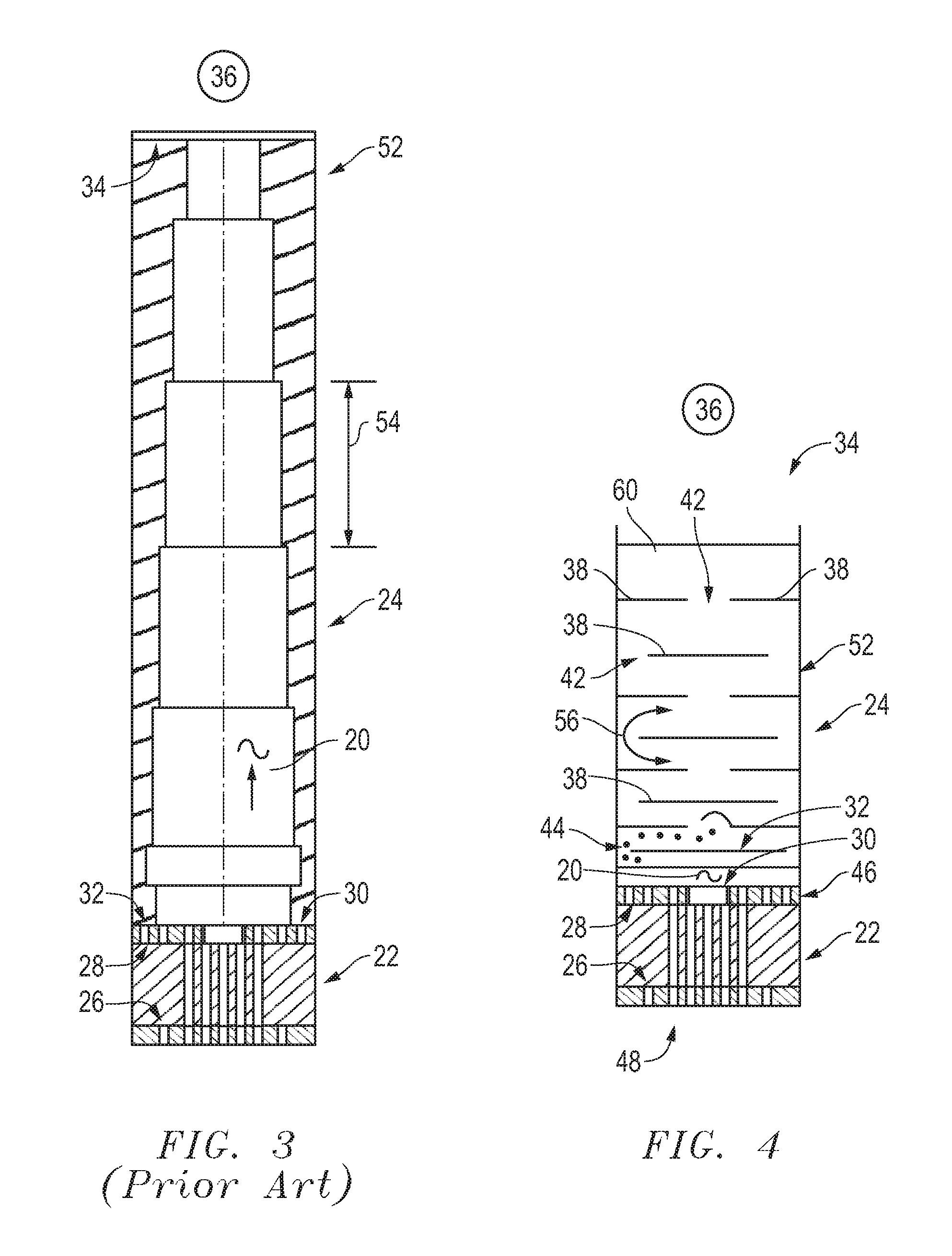
[0025]A radiator or planar antenna array A for conveying or receiving an electronic signal 20 of the type including at least one driver or transceiver segment or substrate 22 and an adjacent transformer to free space segment or section 24. The receiver or driver section 22 is generally formed having a first or lower side 26 and an opposite second or upper face or surface 28. The second side or face 28 further includes at least one point or source 30 for generating a desired electronic wave signal 20 to propagate from the driver segment 22, or for receiving a desired electronic wave signal 20 from the tr...


PUM


Abstract

A radiator (A) has a receiver segment (22) and an adjacent transformer segment (24). The receiver (22) has a first (26) and an opposite second face (28). The second face (28) includes a generator (30) of a signal (20) that propagates from the receiver segment (22). A first face (32) of the transformer segment (24) is formed adjacent to the receiver segment second face (28). A transmitted signal (20) propagates through the transformer segment (24) from the first (32) to a second face (34). A plurality of free floating plates (38) are formed within the transformer segment (24) in layers (40) with gaps (42) permitting signal (20) passage. The floating plates (38) deflect the signal path through the transformer segment (24).

Description

CROSS REFERENCE TO RELATED APPLICATIONS[0001]This application claims the benefit of U.S. Provisional Application Ser. No. 61 / 223,956, filed Jul. 8, 2009, entitled WIDEBAND WIDE SCAN ANTENNA MATCHING STRUCTURE USING ELECTRICALLY FLOATING PLATES.BACKGROUND OF THE INVENTION[0002]1. Technical Field[0003]The invention relates to the field of antennas that propagate an electronic signal, and more particularly to a planar array type of antenna comprising a plurality of signal generating or receiving elements having a transceiver segment substrate with a dielectric substrate formed on top of a signal generating face of the driver segment substrate.[0004]2. Background Art[0005]There are many alternative forms and formats for an antenna that propagates an electronic signal. An antenna often is designed or adapted particularly for a selected frequency range, size, or directional characteristics.[0006]The current state of the art for one wideband antenna design consists of antenna having a subs...

Claims


Application Information

Patent Timeline
Patent Type & Authority Patents(United States)
IPC IPC(8): H01Q13/00
CPCH01Q21/061
Inventor WATERMAN, TIMOTHY G.
Owner NORTHROP GRUMMAN SYST CORP
Why Eureka
Try Eureka