Microelectromechanical microphone carrier module

a microphone carrier and micro-electromechanical technology, applied in the direction of piezoelectric/electrostrictive transducers, electrostatic transducers of semiconductors, transducers, etc., can solve the problems of increased size of conventional mem microphones after packaging, increased production cost, and increased production cost of mem microphones, etc., to reduce production costs, reduce assembly time, and reduce the size of the package

Active Publication Date: 2012-08-28
LINGSEN PRECISION INDS
View PDF8 Cites 3 Cited by
  • Summary
  • Abstract
  • Description
  • Claims
  • Application Information

AI Technical Summary

Benefits of technology

[0007]The primary objective of the present invention is to provide an MEM microphone carrier module, which can decrease the size of its package, need lower production cost, and take less assembly time.

Problems solved by technology

However, such multi-layer or composite substrate is high in production cost and thick in structure, such that the size of the conventional MEM microphone after packaged is increased.
However, in the process of the packaging, it takes more time to mount and position the space member onto the chip carrier.

Method used


Image

  • Microelectromechanical microphone carrier module
  • Microelectromechanical microphone carrier module

Examples


Embodiment Construction

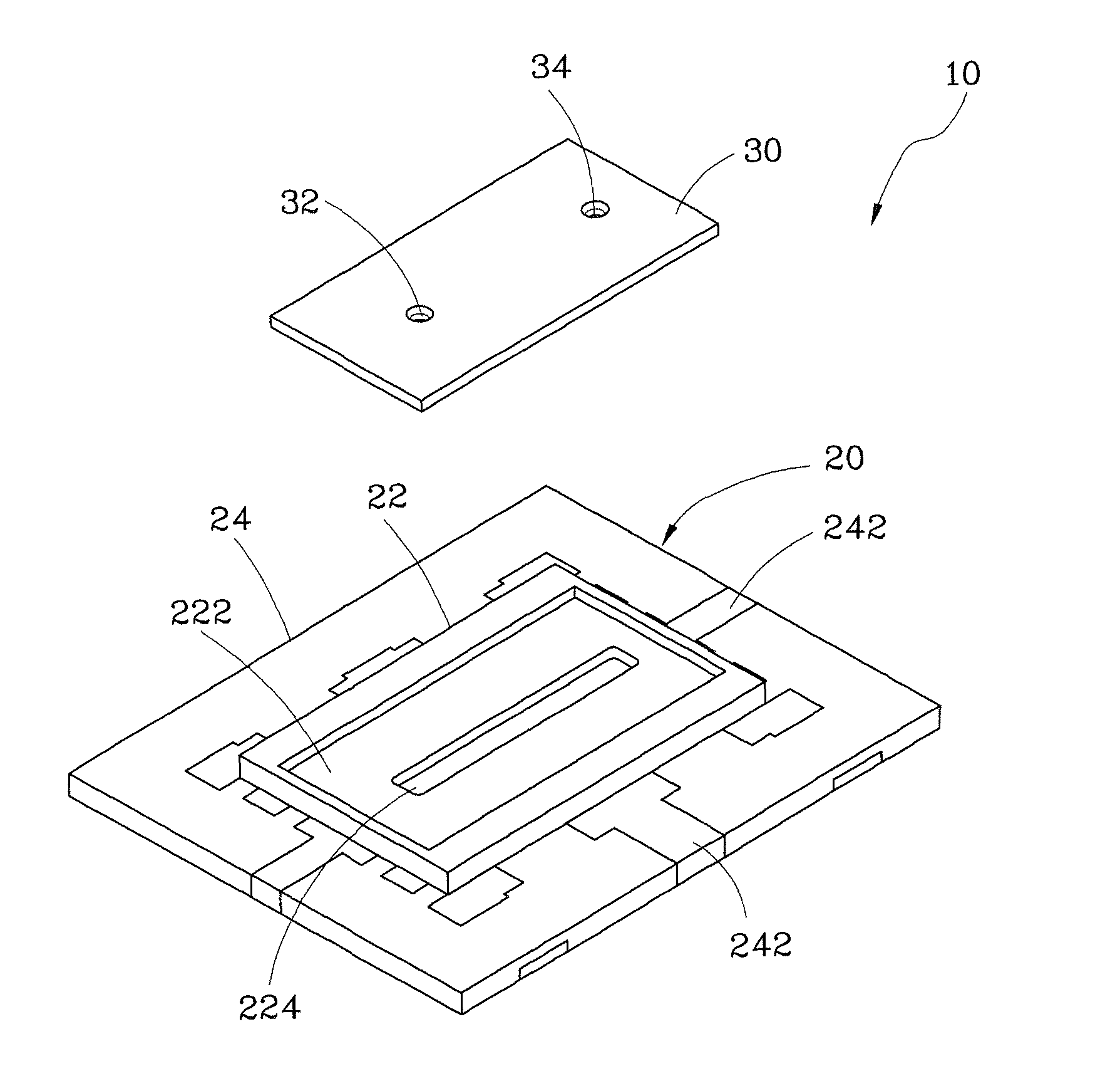
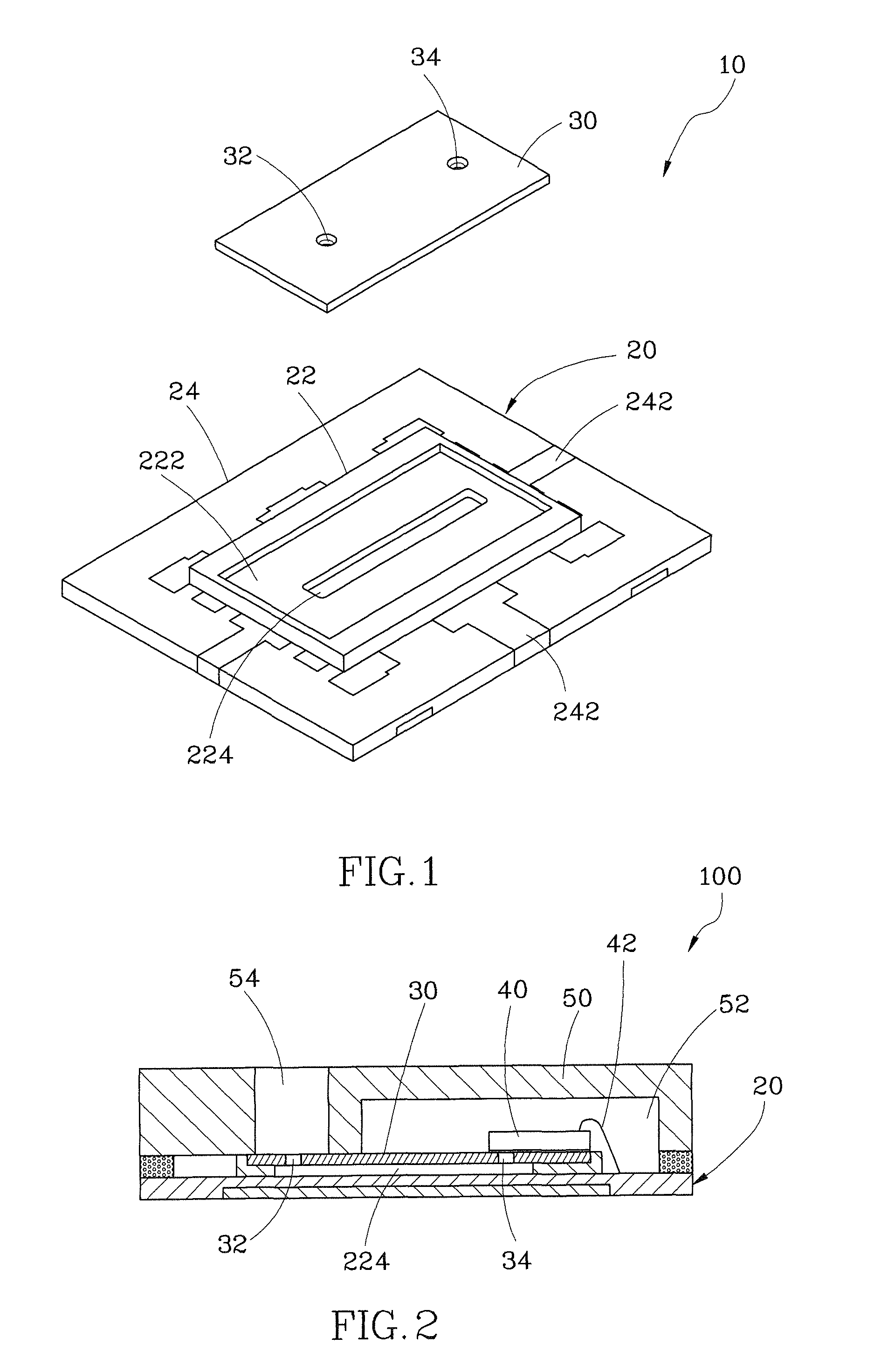
[0012]Referring to FIG. 1, an MEM microphone carrier module 10 constructed according to a first preferred embodiment of the present invention is composed of a substrate 20 and a cover plate 30. The detailed descriptions and operations of these elements as well as their interrelation are recited in the respective paragraphs as follows.

[0013]The substrate 20 is includes a space layer 22 and a bottom layer 24 which are integrally formed by pre-molding.

[0014]The area of the space layer 22 is smaller than that of the bottom layer 24 and located at a center of a top side of the bottom layer 24. A rectangular recession 222 is recessed from a top side of the space layer 22 for facilitating mounting and positioning the cover plate 30 onto the substrate 20. A groove 224 is formed in the recession 222.

[0015]The bottom layer 24 is a square plate and includes a metallic plate 242. The metallic plate 242 defines a predetermined pattern on a surface of the bottom layer 24.

[0016]In addition, the su...


PUM


Abstract

An MEM microphone carrier module is composed of a substrate and a cover plate. The substrate includes a space layer, a bottom layer, a recession recessed from a top side of the space layer, and a groove formed in the recession. The bottom layer has a metallic plate defining a predetermined pattern and exposed outside a surface thereof. The bottom layer is a single-layer structure formed by the molding of the metallic plate and the insulating glue, such that the substrate is thinner to need lower production cost and take less assembly time than the prior art.

Description

BACKGROUND OF THE INVENTION[0001]1. Field of the Invention[0002]The present invention relates generally to a microelectromechanical (MEM) microphone, and more particularly, to an MEM microphone carrier module.[0003]2. Description of the Related Art[0004]Compared with a conventional microphone, an MEM microphone includes the advantages of low interference, small size, and power saving. More and more electronic products are designed to be very compact subject to the dominant trend thereof, so the MEM microphone is taking place of the conventional microphone.[0005]When it is intended to package the conventional MEM microphone, mostly, a multi-layer or composite substrate is used for carrying a chip. However, such multi-layer or composite substrate is high in production cost and thick in structure, such that the size of the conventional MEM microphone after packaged is increased.[0006]In addition, the package of the MEM microphone needs a passage for sound transmission to allow the exte...

Claims


Application Information

Patent Timeline
Patent Type & Authority Patents(United States)
IPC IPC(8): H04R21/02
CPCH04R19/005
Inventor YEH, JEN-CHUANTIAN, JYONG-YUELEE, KUO-TING
Owner LINGSEN PRECISION INDS
Why Eureka
Try Eureka