
Impact resistant door skin, door including the same, and method of manufacturing an impact resistant door skin from a pre-formed door skin

a door and pre-formed technology, applied in the field of impact resistant door skin, can solve the problems of difficult storage, transportation and installation, difficult to store, transport and install, and relatively expensive doors, and achieve the effect of high impact resistan

Active Publication Date: 2012-09-04
MASONITE CORP
View PDF13 Cites 24 Cited by
  • Summary
  • Abstract
  • Description
  • Claims
  • Application Information

AI Technical Summary

Benefits of technology

The patent describes a method of making a high impact resistant door skin by applying adhesive to a preformed door skin and adding a layer of chopped glass fibers coated with adhesive onto a fiberglass mesh mat. This results in a strong and durable door skin that can withstand impacts. The method can be used to reinforce different styles and sizes of preformed door skins. The resulting door skins have a recessed panel and are secured to a peripheral frame with adhesive and chopped glass fibers, making them ideal for use in hollow core doors.

Problems solved by technology

Such doors are relatively expensive and difficult to assemble.
In addition, they are relatively heavy, and therefore difficult to store, transport and install.
Such doors are also relatively expensive.
In addition, they are often less desirable to consumers because they lack aesthetic detail, and may rust and dent.
However, consumers have little choice in the variety of doors that can be made high impact resistant.
That is, consumers typically have a limited number of options for selecting from among styles and sizes of hollow core doors that are made impact resistant.
Additionally, the manufacture of impact resistant hollow core doors typically requires a substantial amount of equipment and capital, thus making impact resistant doors relatively expensive to manufacture.

Method used


Image

  • Impact resistant door skin, door including the same, and method of manufacturing an impact resistant door skin from a pre-formed door skin
  • Impact resistant door skin, door including the same, and method of manufacturing an impact resistant door skin from a pre-formed door skin
  • Impact resistant door skin, door including the same, and method of manufacturing an impact resistant door skin from a pre-formed door skin

Examples


Embodiment Construction

[0023]Reference will now be made in detail to the embodiments and methods of the invention as illustrated in the accompanying drawings, in which like reference characters designate like or corresponding parts throughout the drawings. It should be noted, however, that the invention in its broader aspects is not limited to the specific details, representative devices and methods, and illustrative examples shown and described in this section in connection with the preferred embodiments and methods. The invention according to its various aspects is particularly pointed out and distinctly claimed in the attached claims read in view of this specification, and appropriate equivalents.

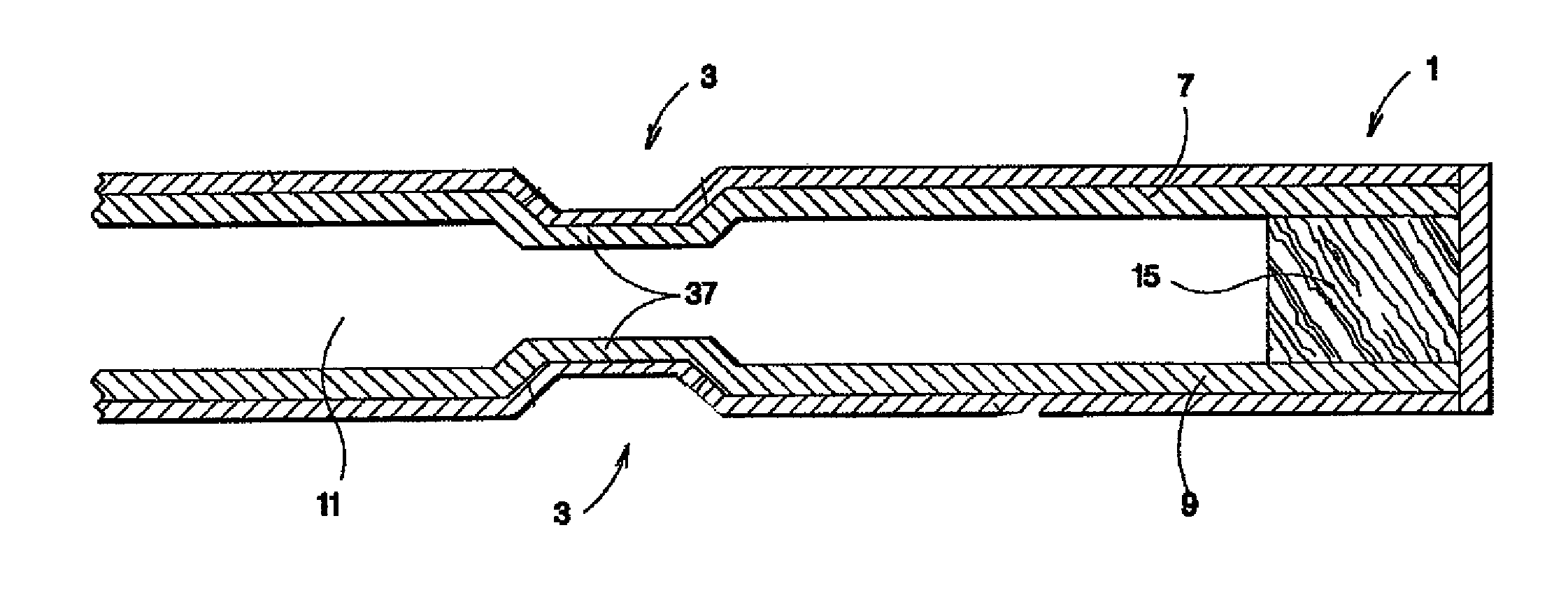
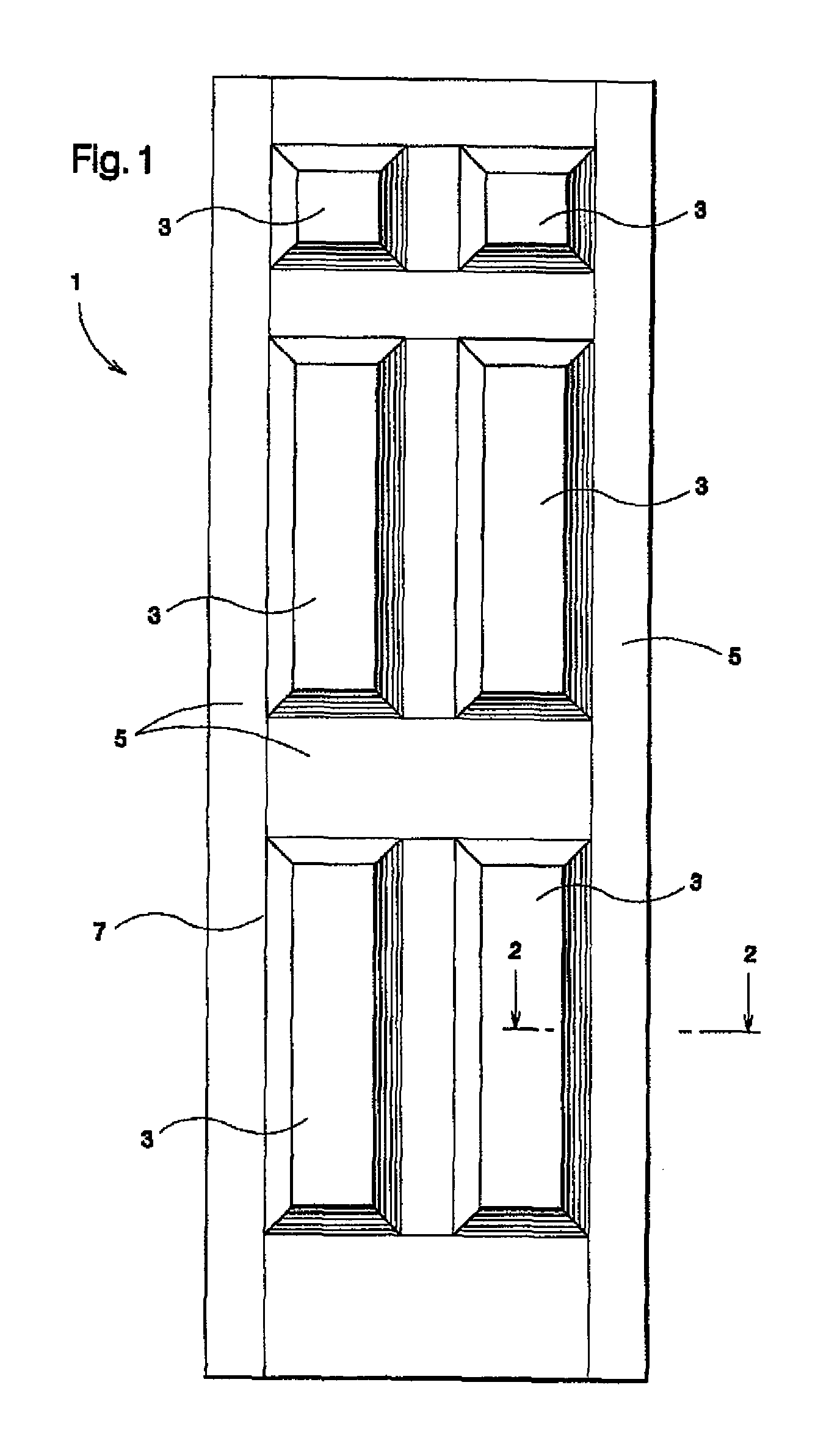
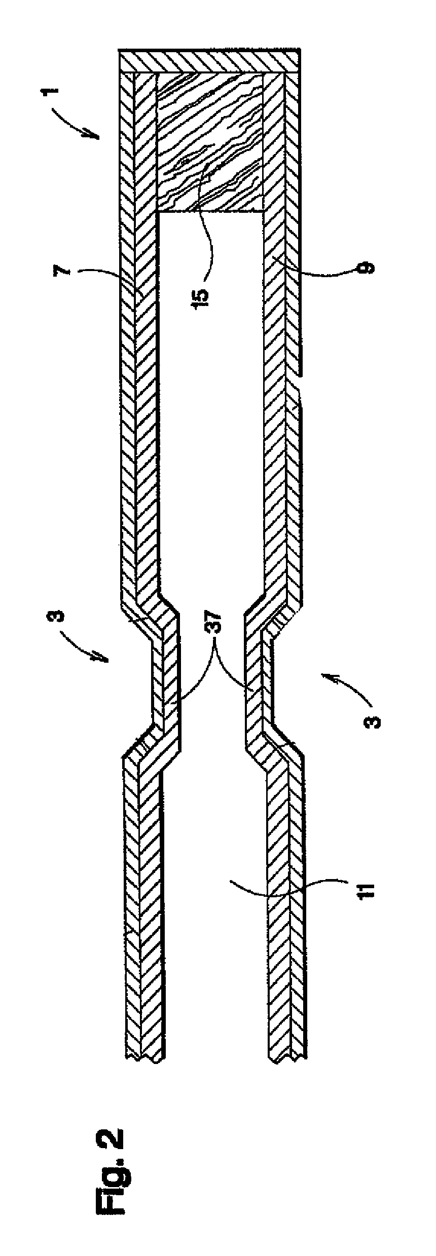
[0024]As best shown in FIGS. 1 and 2, an exemplary hollow core door 1 includes molded door skins 7 and 9. The door skins 7 include three-dimensional recessed panels 3 and raised panels 5 and may be manufactured from sheet molding composition (SMC) or other suitable polymeric material. Door skins 7 and 9 of doo...


PUM

PropertyMeasurementUnit
speedaaaaaaaaaa
speedaaaaaaaaaa
velocityaaaaaaaaaa

Abstract

An impact resistant door skin, a door including the same, and a method of manufacturing an impact resistant door skin from a pre-formed door skin are provided. The method includes the steps of providing at least one preformed door skin and applying adhesive to a rear side of the at least one preformed door skin. A fiberglass mesh mat is pressed onto the rear side of the at least one preformed door skin. Then, chopped glass fibers coated with adhesive are sprayed onto the rear side of the at least one preformed door skin using a chopper gun to form a layer of chopped glass fibers on the fiberglass mesh mat. The performed door skin may be a molded door skin having at least one recessed panel formed therein.

Description

CROSS REFERENCE TO RELATED APPLICATION AND CLAIM TO PRIORITY[0001]This application is based on provisional application Ser. No. 61 / 035,780, filed Mar. 12, 2008, the disclosure of which is incorporated herein by reference and to which priority is claimed under 35 U.S.C. §119(e).FIELD OF THE INVENTION[0002]The present invention relates to an impact resistant door skin, a door including the same, and a method of manufacturing an impact resistant door skin from a pre-formed door skin.BACKGROUND OF THE INVENTION[0003]As known in the art, door facings also known as “door skins” may be secured to a support structure or frame to form a hollow core door. Such facings may be molded from a polymeric material, such as sheet molding compound (“SMC”). SMC may be molded to form a door facing including one or more depressions or grooves, such as one or more square or rectangular depressions. These depressions may define the perimeter of one or more simulated panels. Alternatively, the facings may b...

Claims


Application Information

Patent Timeline
Patent Type & Authority Patents(United States)
IPC IPC(8): E04C1/00
CPCE06B3/822B32B5/26B29D99/0021B32B37/24E06B3/7001E06B3/80B32B2309/02Y10T156/1031B32B2375/00B32B2419/00B32B2607/00E06B2003/7023E06B2003/7051B32B17/02B29L2031/724B32B2309/04Y10T442/10
Inventor PFAU, JAMESHART, STEPHENBRYANT, JAMES
Owner MASONITE CORP
Learn More