Ice bagging apparatus

a bagging apparatus and bagging technology, applied in the field of ice bagging apparatus, can solve the problems of water freezing the ice cubes together into bigger solid blocks, condensation entering some of the ice bags,

Active Publication Date: 2012-09-04
REDDY ICE LLC
View PDF35 Cites 13 Cited by
  • Summary
  • Abstract
  • Description
  • Claims
  • Application Information

AI Technical Summary

Benefits of technology

[0034]According to a further aspect of the invention the second ice transport system may be upwardly directional. Hereby it is possible to minimize the risk that water is introduced into the first collection zone during the defrost cycle of the ice supply.
[0085]It is herewith achieved that the amount of ice dispensed by the first ice transport system into the ice bag may be measured by weight. As the value of the ice may be settled by weight it is advantageous to measure the weight during filling and verify the weight of the filled bag.

Problems solved by technology

This causes condensate to enter some of the ice bags during filling when the ice maker has completed a defrost cycle.
A disadvantage of this is that the water freezes the ice cubes together into bigger solid blocks, which is not desired by the end customer of the ice cubes.

Method used


Image

  • Ice bagging apparatus
  • Ice bagging apparatus
  • Ice bagging apparatus

Examples


Embodiment Construction

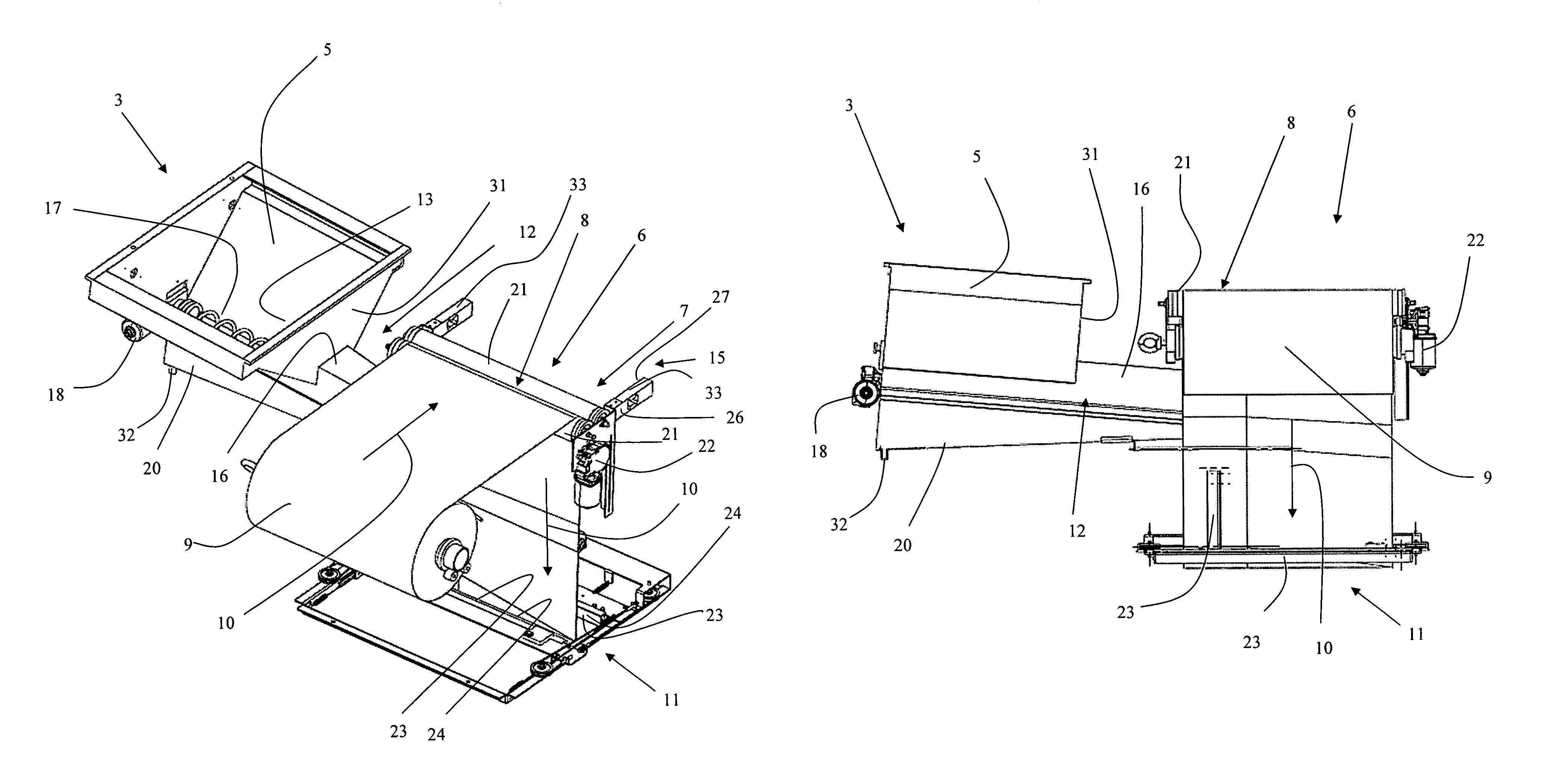
[0007]According to one aspect the present invention, this is achieved by an ice bagging apparatus comprising:

a) a frame,

b) a first ice collecting zone within said frame comprising a collecting bin;

c) an ice bagging zone within said frame comprising

[0008]i) a film feeding mechanism for conveying two superposed heat-sealable elongated film webs of plastic from a film web stock according to a conveying direction, and[0009]ii) a welding apparatus for joining said two film webs to form a bag,

d) a first ice transport system within said frame, having an inlet opening in the first ice collecting zone and an outlet opening in the ice bagging zone and positioned between the two film webs above the formed bag, and

e) a measuring arrangement within said frame for measuring the amount of ice dispensed into the bag by the first ice transport system.

[0010]It is further achieved by an ice bagging apparatus comprising:

a) a first ice collecting zone comprising a first collecting bin;

b) a second ice co...


PUM

PropertyMeasurementUnit
heat-sealableaaaaaaaaaa
sizeaaaaaaaaaa
gravityaaaaaaaaaa

Abstract

An ice bagging apparatus which has a frame defining a first ice collecting zone with a collecting bin and an ice bagging zone, wherein the ice bagging zone has a film feeding mechanism that conveys two heat-sealable elongated plastic film webs and a welding apparatus to form a bag from the webs. The film feeding mechanism has rollers between which film webs are passed and pressed against each other. A measuring arrangement measures ice dispensed into the bag by a first ice transport system positioned between the two film webs that form the bag.

Description

FIELD OF THE INVENTION[0001]The present invention relates to an ice bagging apparatus for bagging discrete units of ice.[0002]The present invention further relates to a combination of an ice making machine, an ice bagging apparatus, an ice storage compartment and an ice bag collector and distributor apparatus.BACKGROUND OF THE INVENTION[0003]An example of an ice bagging apparatus is disclosed in U.S. Pat. No. 4,368,608. This apparatus comprises an ice maker, which is placed above an ice collecting and bagging zone, and wherein the ice maker dispenses ice directly into a bag. This causes condensate to enter some of the ice bags during filling when the ice maker has completed a defrost cycle.[0004]A disadvantage of this is that the water freezes the ice cubes together into bigger solid blocks, which is not desired by the end customer of the ice cubes.[0005]Another example of an ice bagging apparatus is disclosed in U.S. Pat. No. 5,109,651. This apparatus comprises an ice collecting zo...

Claims


Application Information

Patent Timeline
Patent Type & Authority Patents(United States)
IPC IPC(8): B65B1/32B65B1/46B65B9/02
CPCB65B1/06B65B1/32B65B9/073B65B51/26B65B51/303F25C5/18F25D2331/801
Inventor PAPE, HENRIK
Owner REDDY ICE LLC
Why Eureka
Try Eureka