Refrigerating device with circulating air cooling system

Active Publication Date: 2012-09-04
MIELE & CO KG +1
View PDF8 Cites 5 Cited by
  • Summary
  • Abstract
  • Description
  • Claims
  • Application Information

AI Technical Summary

Benefits of technology

[0002]The object of the present invention is to create a refrigerating device with a circulating air cooling system which allows good storage conditions to be created for cooled items sensitive to drying out or for cooled items sensitive to moisture.
[0007]Preferably this frame has openings which in the first position are flush with the air passage openings. Thus the frame can lie flat against the dividing wall in the first position without disturbing the flow of the air from the distribution chamber into the compartment.

Problems solved by technology

The airflow slowed down by the diffusion layer can however result in condensation water only being removed inadequately from the compartment.
Thus the cooled items sensitive to an excess of moisture can become soaked in the compartment, which is also not desired.

Method used


Image

  • Refrigerating device with circulating air cooling system
  • Refrigerating device with circulating air cooling system
  • Refrigerating device with circulating air cooling system

Examples


Embodiment Construction

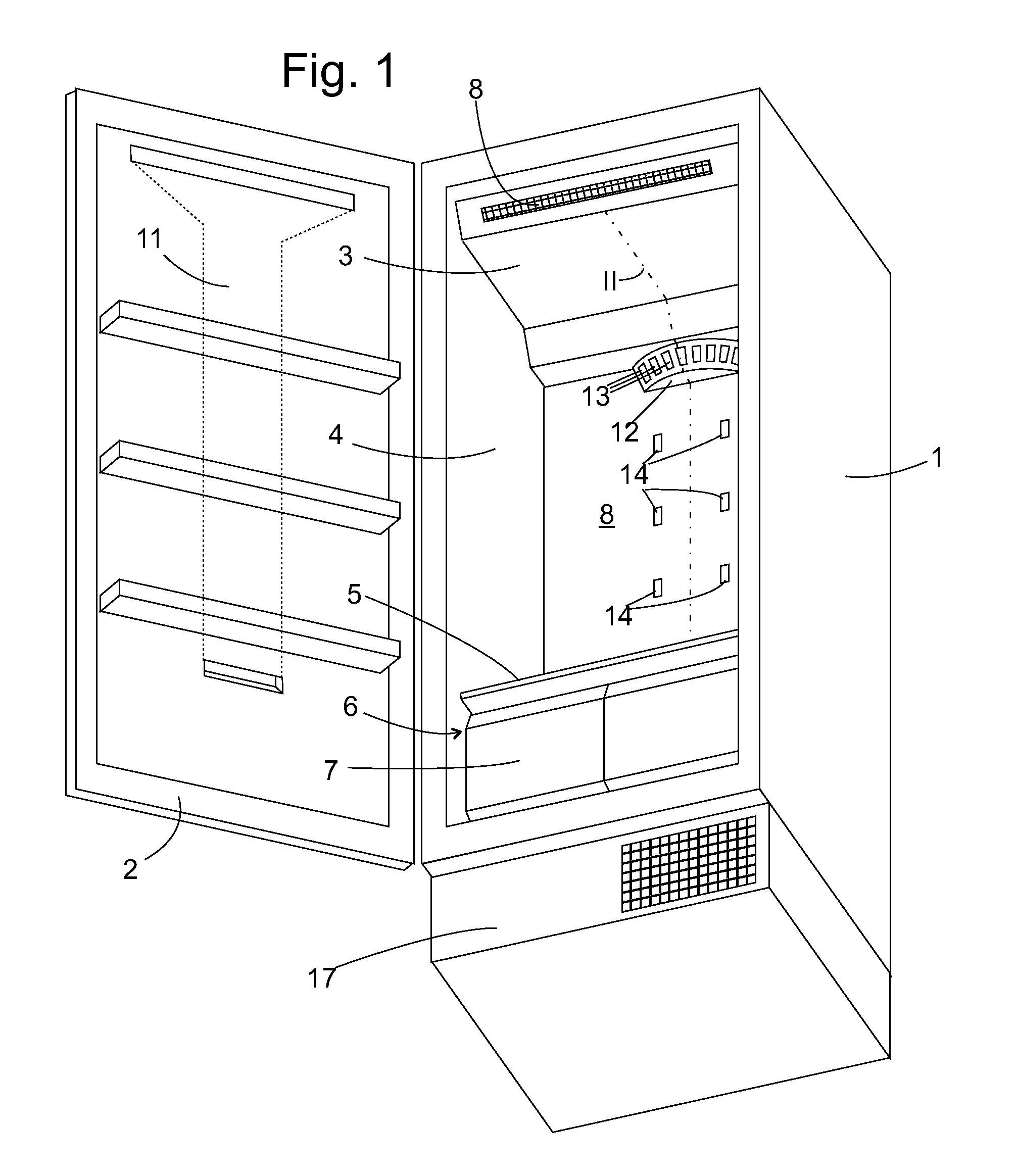
[0024]FIG. 1 shows a perspective view at an angle from below of a refrigerating device with reference to which the present invention is to be explained. The device has a carcass 1 and a door 2 closing onto it. The inside of the carcass 1 is divided into an evaporator area 3 at the top below the roof of the carcass 1, a first cooling area 4, and separated from this by an insulating dividing wall 5, a second cooling area 6. The second cooling area 6 is divided into two compartments by pull-out drawers 7 arranged next to each other. The first cooling area 4 is normally divided by a number of cooled item carriers into compartments lying above one another. These cooled item carriers are omitted in FIG. 1 since they are not of importance for the current invention.

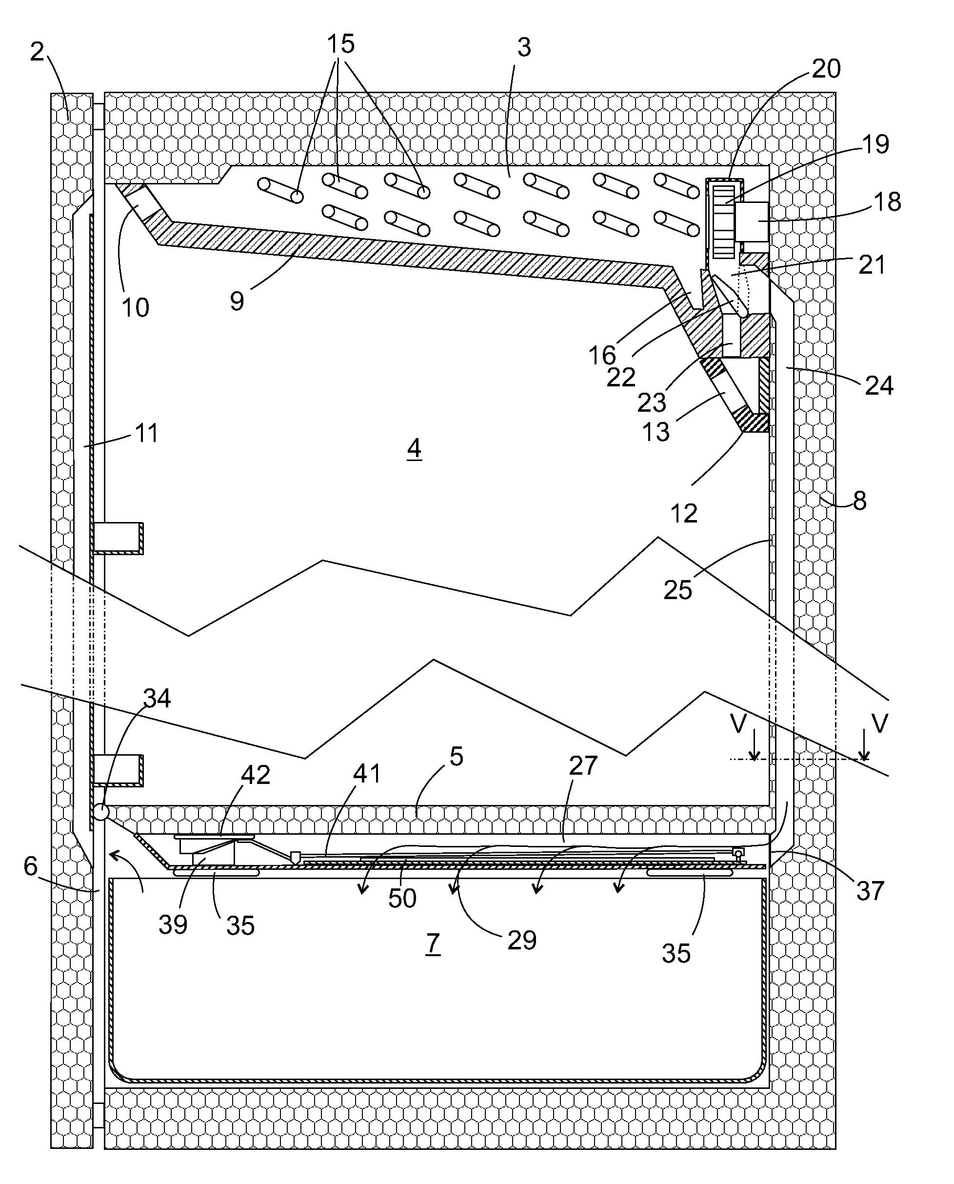
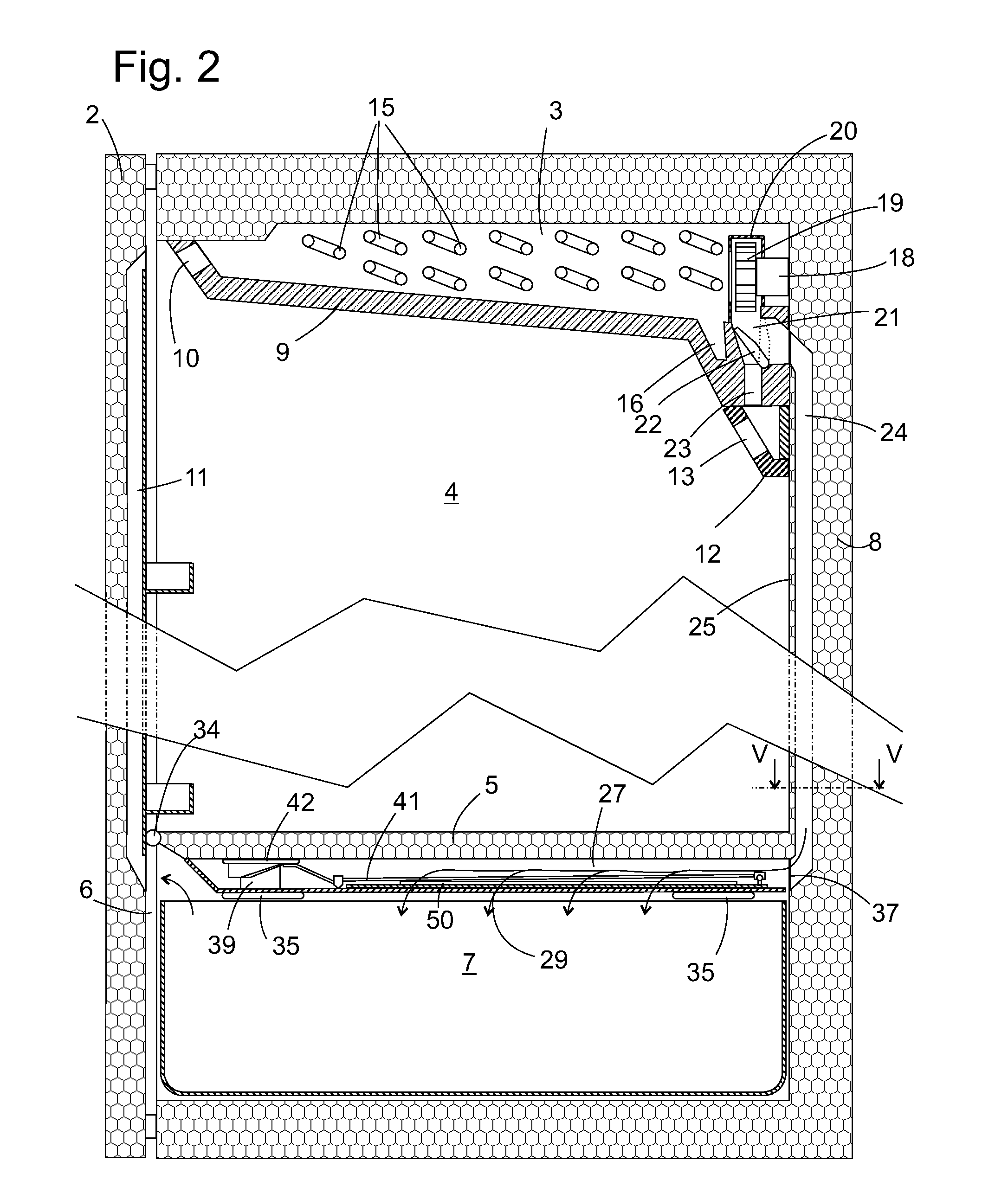
[0025]Formed on the front side of a dividing wall 9 separating the evaporator area 3 from the first cooling area 4 (see FIG. 2) is an air inlet opening 10 through which air can enter from the first cooling area 4 into the evapora...


PUM


Abstract

A refrigerating device is provided that includes an evaporator and a compartment that is cooled by air circulating air from and to the evaporator, wherein a diffusion layer can be displaced between a first position, in which air passage openings distributed in a wall separating the compartment from a distribution chamber are covered by the diffusion layer, and a second position, in which the diffusion layer is positioned so as to allow air to flow from the evaporator through the distribution chamber into the compartment while bypassing the diffusion layer.

Description

BACKGROUND OF THE INVENTION[0001]The present invention relates to a refrigerating device with circulating air cooling system and at least one compartment cooled by circulating air from and to the evaporator. In a refrigerating device of this type known from DE 10 2005 021 560 A1 a distribution chamber of formed adjacent to the cooling compartment which is separated from said compartment by a perforated wall. The holes can be covered on the distribution chamber side by a fleece in order to prevent a fierce stream of cold air from the distribution chamber hitting sensitive cooled items in the compartment and drying them out. The airflow slowed down by the diffusion layer can however result in condensation water only being removed inadequately from the compartment. Thus the cooled items sensitive to an excess of moisture can become soaked in the compartment, which is also not desired.BRIEF SUMMARY OF THE INVENTION[0002]The object of the present invention is to create a refrigerating de...

Claims


Application Information

Patent Timeline
IPC IPC(8): F25D17/06
CPCF25D17/042F25D17/045F25D17/065F25D2317/04131F25D2317/061F25D2317/0655F25D2317/0665F25D25/025
Inventor BISCHOFBERGER, THOMASHAGELE, FRITZIHLE, HANSKEMPTE, ANDREASPLACKE, FRANKSPAAG, RAINERSTAHL, MATTHIASVAN PELS, ULRICH
Owner MIELE & CO KG
Why Eureka
Try Eureka