Multi-wire saw and method for cutting ingot

a multi-wire saw and ingot technology, which is applied in the field of multi-wire saws for cutting an, can solve the problems of increasing the probability of disengagement of the wire from the guide groove, chipping on the edge of the wafer, and increasing the probability of the wire being cut out of the guide groove, so as to improve the yield of non-defective wafers and reduce the thickness variation of the edges of the wafer cut out from the material to be machined

Inactive Publication Date: 2012-09-04
MITSUBISHI ELECTRIC CORP
View PDF9 Cites 5 Cited by
  • Summary
  • Abstract
  • Description
  • Claims
  • Application Information

AI Technical Summary

Benefits of technology

[0011]The present invention has an effect that the thickness variation of the edges of the wafers cut out from the material to be machined can be reduced to improve the yield of non-defective wafers by restraining the wire from being lifted at the start of cutting the material to be machined, and preventing the wire from being displaced in the guide grooves on the wire guide rollers and being disengaged from the guide grooves.

Problems solved by technology

Such processes are repeatedly performed for a large number of times. Therefore, a wafer having a thin edge cannot withstand such pressing force that is repeatedly applied thereto, resulting in producing cracks or chips on the edge of the wafer and the wafer becomes defective.
However, the narrower pitch makes the guide grooves formed on the wire guide rollers shallow, so that increasing the probability of disengagement of the wire from the guide grooves increases.
In the worst scenario, the wire might be tangled and broken and thus non-defective wafers cannot be obtained at all.
These problems, such as the displacement in the guide grooves and the disengagement of the wire from the guide grooves on the wire guide rollers, predominantly arise after completion of cutting the silicon ingot.

Method used


Image

  • Multi-wire saw and method for cutting ingot
  • Multi-wire saw and method for cutting ingot
  • Multi-wire saw and method for cutting ingot

Examples


first embodiment

[0045

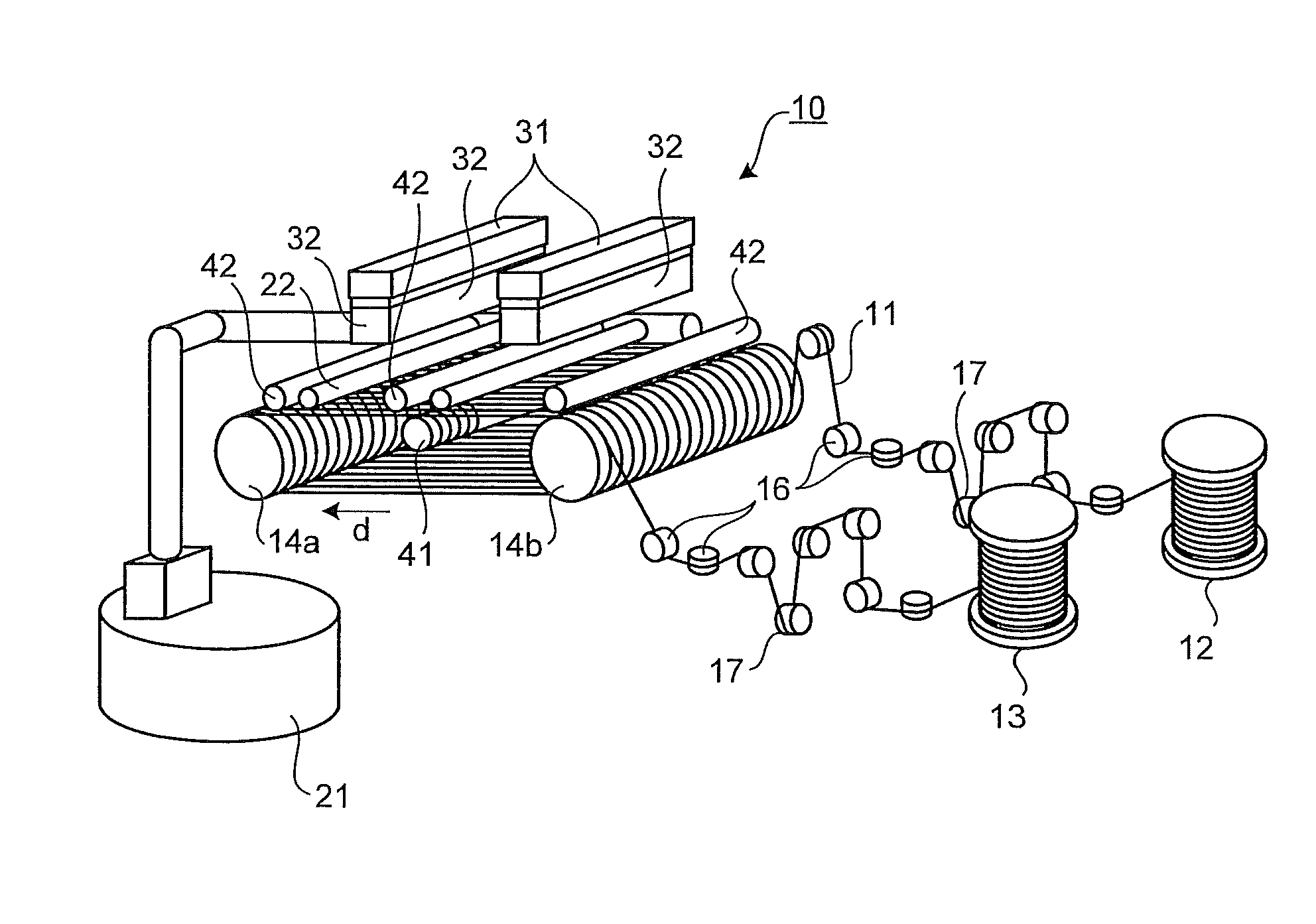
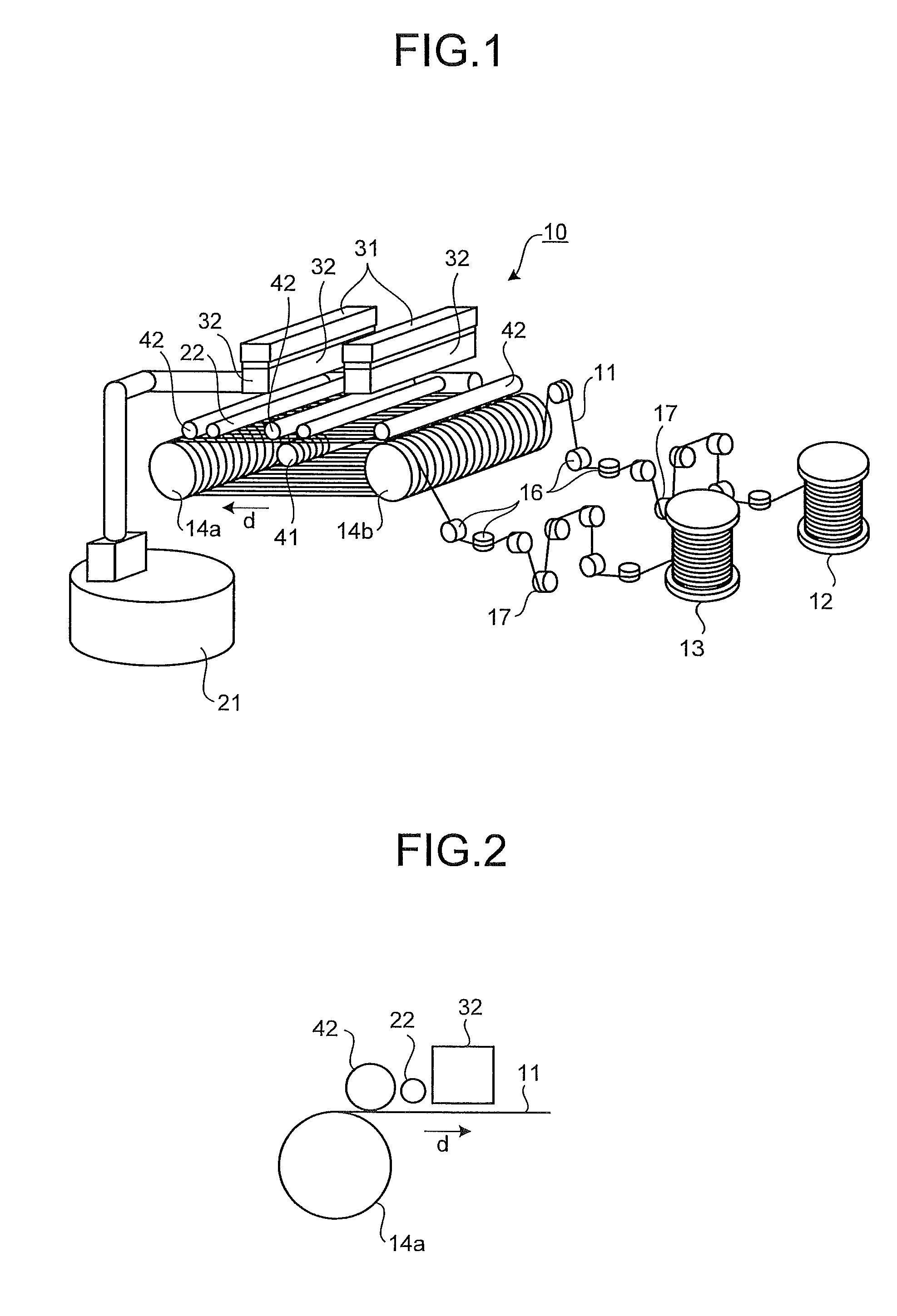
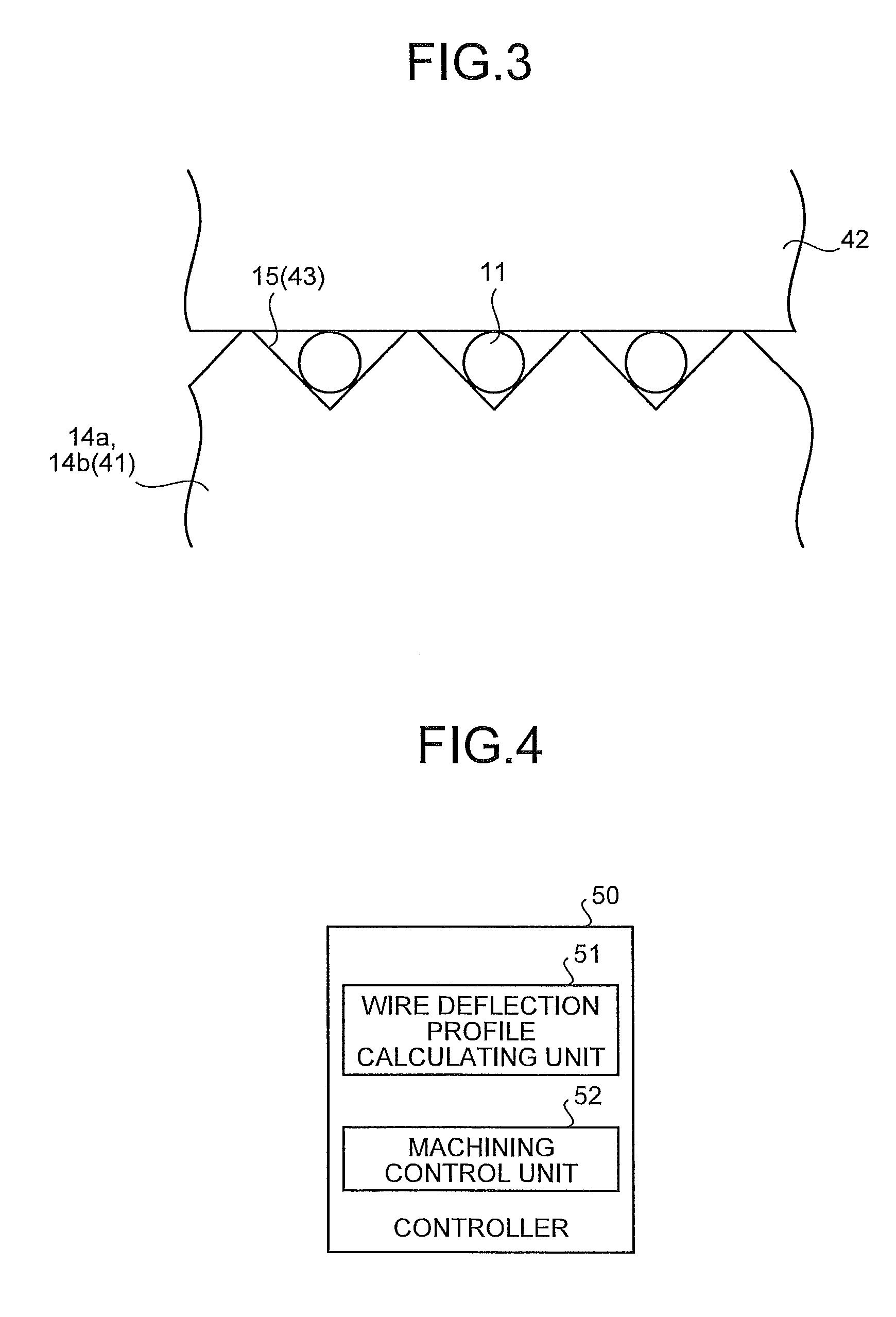
[0046]FIG. 1 is a perspective view showing a main part of a multi-wire saw according to the present invention, FIG. 2 is a side view of the structure near a wire guide roller seen from a direction of the rotation axis of the wire guide roller, and FIG. 3 is a schematic diagram showing a relationship between a wire restraining unit and the wire guide rollers.

[0047]As illustrated in FIG. 1, a multi-wire saw 10 includes a wire 11; a wire-feeding mechanism 12 that feeds the wire 11; a wire winding-up mechanism 13 that winds up the fed wire 11; two wire guide rollers 14a and 14b that are disposed between the wire-feeding mechanism 12 and the wire winding-up mechanism 13 such that the rotation axes of the rollers are parallel to each other; a plurality of guide rollers 16 that guides the wire 11 traveling from the wire-feeding mechanism 12 to the wire guide roller 14a and guides the wire 11 from the wire guide roller 14b to the wire winding-up mechanism 13; and a tension roller 17 th...

second embodiment

[0055

[0056]FIG. 4 is a functional block diagram showing a controller of the multi-wire saw. A controller 50 includes a wire deflection profile calculating unit 51, and a machining control unit 52. The configuration of the multi-wire saw 10 controlled by the controller 50 is the same as that of the first embodiment in FIG. 1, therefore, the explanation thereof will be omitted.

[0057]The wire deflection profile calculating unit 51 derives deflection of the wire 11 at a predetermined cutting position at the point where a depth of a kerf formed at the start of cutting of the ingots 32 is at least equal to or larger than the radius of the wire 11. FIG. 5 is a schematic sectional view showing a state of an ingot cut to a depth e at the start of cutting of the ingot, and FIG. 6 is a schematic diagram showing a state in which the multi-wire saw is seen from the direction of the rotation axes of the wire guide rollers at the start of cutting. In FIG. 5, a state in which the ingot 32 is cut to...

third embodiment

[0066

[0067]The wire-lifting restraining member 42 that prevents the wire 11 from being lifted, as described in the first and the second embodiments, may be a cylindrical body of rotation having a cylindrical surface with grooves at the same pitch as that of the guide grooves 15 and 43 formed on the wire guide rollers 14a, 14b, and 41.

[0068]According to a third embodiment, obtained is an effect of enabling the side run-out of the wire to be further suppressed at the moment of starting of cutting by forming the guide grooves on the surface of the wire-lifting restraining member 42, thereby further reducing the thickness variation of the edges of the wafers compared with a case where a cylindrical body of rotation having nothing formed on a surface thereof is used.

[0069]The effects when the ingot is cut with the multi-wire saw 10 according to the first, the second, and the third embodiments will be explained below. Experiments in cutting were conducted in three rounds for each of the f...


PUM

PropertyMeasurementUnit
speedaaaaaaaaaa
diameteraaaaaaaaaa
lengthaaaaaaaaaa

Abstract

To provide a multi-wire saw that, at the start of cutting of an ingot, prevents a wire from being displaced in grooves of guide rollers due to the wire being lifted. A wire is wound around a plurality of wire guide rollers to be positioned in a feeding direction of an ingot, and in this state, a wire-lifting restraining member that is a body of rotation and restrains the wire from being lifted by being brought into contact with the wire is disposed near the wire guide rollers.

Description

TECHNICAL FIELD[0001]The present invention relates to a multi-wire saw for cutting an ingot for manufacturing wafers, and a method for cutting an ingot.BACKGROUND ART[0002]A multi-wire saw with which a large number of wafers can be cut out at once with a relatively small cutting allowance has been used for cutting a silicon ingot. The multi-wire saw is configured such that a wire fed from a wire-feeding mechanism is wound around between two wire guide rollers at a pitch of about 0.3 to 0.4 millimeter, and the wire is wound up by a wire winding-up mechanism. A tension roller that constantly applies a predetermined tension to the wire is provided in between the wire-feeding mechanism and the wire guide rollers, and in between the wire guide rollers and the wire winding-up mechanism. In the thus configured multi-wire saw, the wire-feeding mechanism, the two wire guide rollers and the wire winding-up mechanism are synchronously controlled to be driven and the position of the tension rol...

Claims


Application Information

Patent Timeline
Patent Type & Authority Patents(United States)
IPC IPC(8): B28D1/06
CPCB23D57/0023B23D57/0061B24B27/0633B28D5/045
Inventor KAWASAKI, TAKAFUMIMIMURA, SEIICHINISHIDA, HIROKAZU
Owner MITSUBISHI ELECTRIC CORP
Why Eureka
Try Eureka