Coupling apparatus for positioning components in workpiece interior and method of using same

a technology of positioning components and coupling apparatus, which is applied in the direction of domestic articles, mechanical control devices, lamination, etc., can solve the problems of premature failure of composite finished articles, etc., and achieve the effect of accurately mounting and/or coupling components

Active Publication Date: 2012-09-04
SPM AUTOMATION CANADA
View PDF4 Cites 13 Cited by
  • Summary
  • Abstract
  • Description
  • Claims
  • Application Information

AI Technical Summary

Benefits of technology

[0006]Accordingly, one object of the present invention is to provide an improved system and method for accurately mounting and / or coupling a component to a contact surface which is disposed along an interior portion of a hollow formed workpiece.
[0008]A further object of the invention is to provide a hot plate welding system for the accurate melting and / or mounting of thermoplastic components to an interior contact surface of a hollow blow molded workpiece, and wherein the position of the interior contact surface is determined in relation to one or more optically identified features provided on the workpiece exterior.

Problems solved by technology

Heretofore, however, the accurate positioning and mounting / heat fusing of components to interior contact surfaces has presented challenges in ensuring that the component is accurately located at the desired position within the workpiece interior.
Such manufacturing processes, however, suffer the disadvantage that the composite finished article may be subject to premature failure by reason of the partial separation of the joined seams.

Method used


Image

  • Coupling apparatus for positioning components in workpiece interior and method of using same
  • Coupling apparatus for positioning components in workpiece interior and method of using same
  • Coupling apparatus for positioning components in workpiece interior and method of using same

Examples


Embodiment Construction

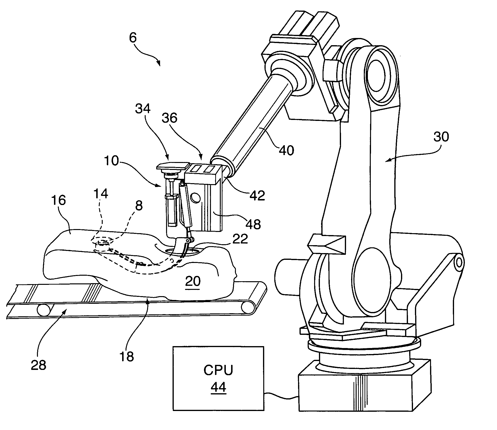
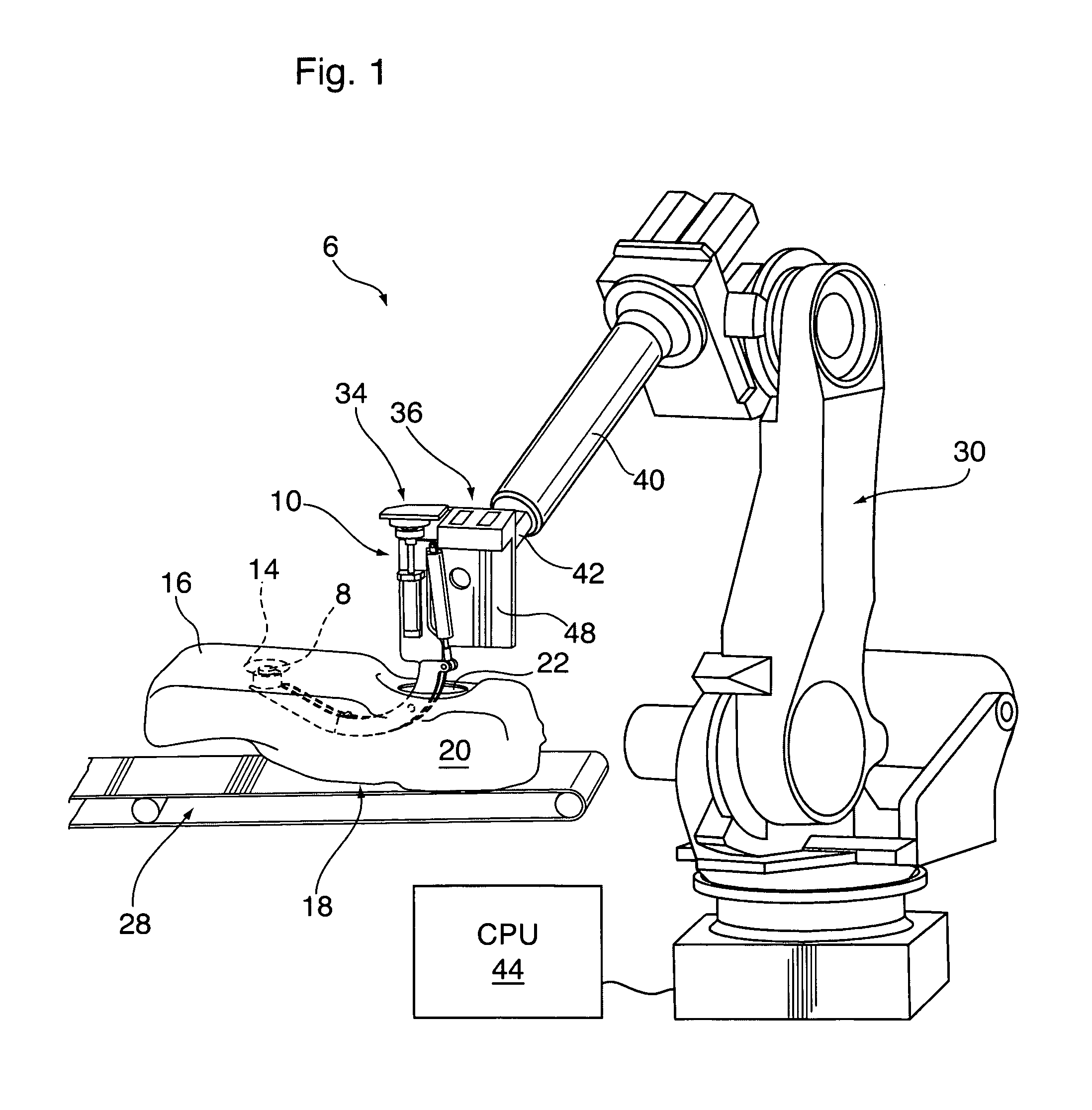
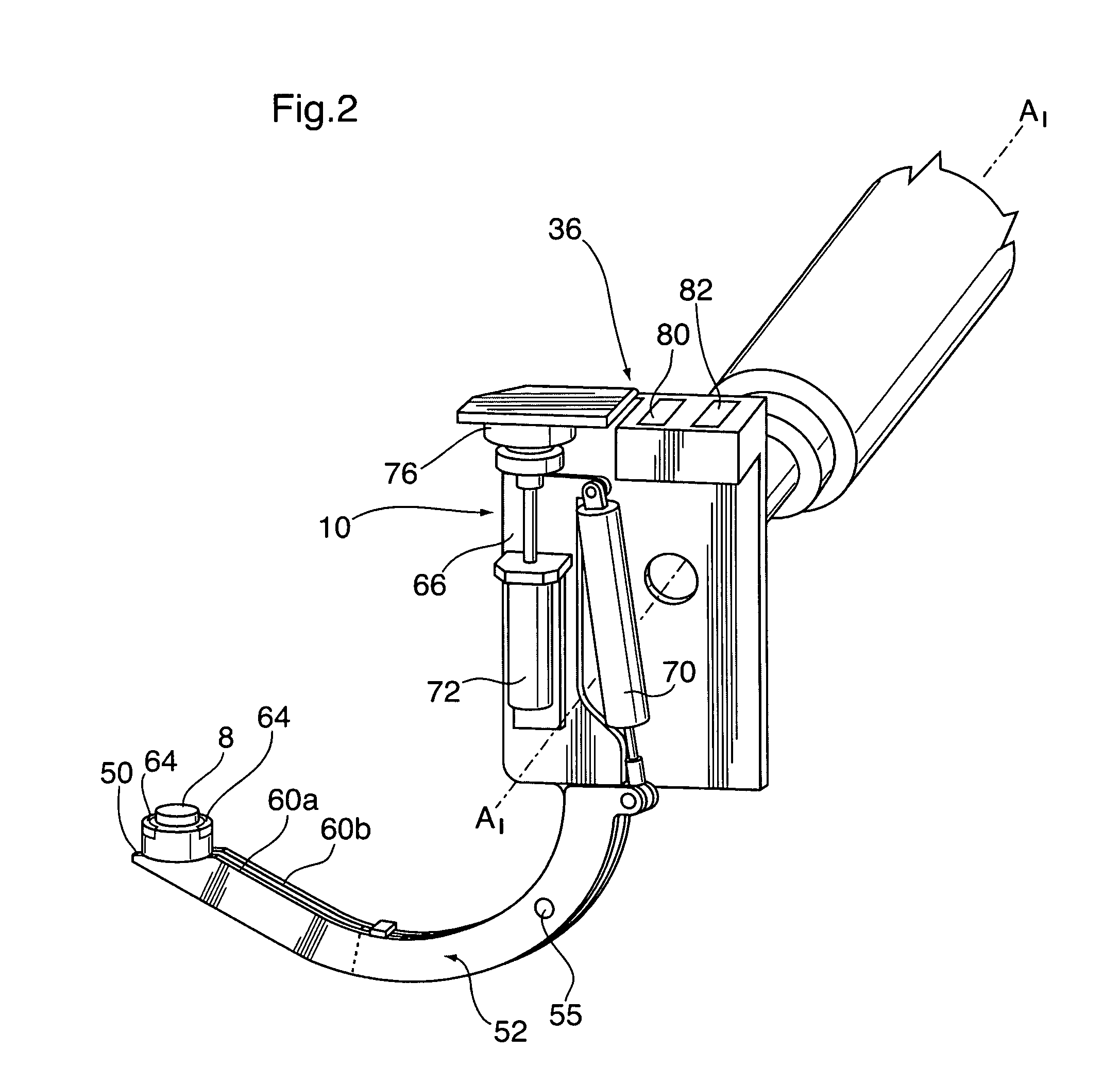
[0035]As will be disclosed, the present invention provides a component coupling apparatus 10 used in finished article manufacture in the securement of a variety of different types of components, including but not limited to valves, mounts, pipes, plugs or filler necks 8, to a desired contact surface 14 disposed along the interior of a hollow workpiece 18. As shown best in FIG. 1 workpiece 18 is formed as a blow molded construction having a unitary sidewall 16 and may for example, comprise a preform for a fluid reservoir or vehicle fuel tank. Although not essential, in a most preferred construction, the workpiece sidewall 16 is formed having a multilayer composite construction, and which incorporates both HDPE and EVOH layers. In the illustrated embodiment, a top side of the workpiece 18 is provided with an access opening 22 through the sidewall 16 which leads into a hollow interior 20, and which is spaced a desired distance from the contact surface 14.

[0036]As shown best in FIGS. 4a...


PUM

PropertyMeasurementUnit
distanceaaaaaaaaaa
movementaaaaaaaaaa
chemical bondingaaaaaaaaaa

Abstract

A component coupling apparatus for mounting a component to an internal contact surface of a hollow workpiece which includes a positioning unit and at least one component holding unit. The component positioning unit includes a processor having memory which pre-stores data representative of a workpiece target feature and an access opening therein. The component positioning unit includes a 3D laser scanner / digitizer which is movable to scan the exterior surface of the workpiece and identify the axial centers of the access opening and target feature, and calculate the distance and / or directional vector therebetween. The component holder unit includes component holder supported on a support arm. The component holder releasably secures the component to be joined to the workpiece, and is sized for insertion at through the access opening to move the component into alignment with the contact surface. The processor controls movement of the carrying arm in directional movement in relation to the scanned distance between the access opening and the target feature, by providing control signals to a robot used to selectively activate position the component holder in response to identified and triangulated relative distances between the access opening and target features.

Description

RELATED APPLICATIONS[0001]This application is related to the applicant's co-pending U.S. patent application Ser. No. 12 / 929,722, entitled “Hot Plate Welding System”, and which was filed in the United States Patent Office on 11 Feb. 2011.SCOPE OF THE INVENTION[0002]The present invention relates to a component positioning apparatus for mounting of workpiece components, and its method of use in the automated positioning and / or securement a component to predetermined contact surfaces disposed along an interior of a hollow workpiece. More preferably, the invention relates to a hot plate welding system operable to partially melt and join components and workpieces made of thermoplastics or other heat fusible materials in the production of finished articles.BACKGROUND OF THE INVENTION[0003]Hot plate welding systems are known for heat welding various types of components, such as plastic seal plugs, filler necks, brackets, vent nipples and the like to thermoplastic workpieces such as fluid re...

Claims


Application Information

Patent Timeline
Patent Type & Authority Patents(United States)
IPC IPC(8): B32B37/00
CPCB25J15/0019B29C66/61B29C65/2084B60K15/03177B29C65/7838B29C66/532B29C66/8221B29C66/8242B29C66/8324B29C66/863B29C65/7817B29L2031/7172B29C66/71B29C66/7234B29K2023/065B29K2023/086B60K2015/03046B60K2015/03453B60K2015/0346B29C65/203B29C66/12461B29C66/126B29C66/73921
Inventor WEBER, WOLFGANGLANE, CORYNOVAKOVIC, BORIS
Owner SPM AUTOMATION CANADA
Why Eureka
Try Eureka