
Air diverter for vehicle cooling system

a technology of cooling system and air diverter, which is applied in the direction of indirect heat exchangers, machines/engines, light and heating apparatus, etc., can solve the problems of degrading the cooling function of the downstream radiator, and achieve the effect of reducing the heat transfer to the radiator coolant, improving the operation of the cooling system, and rejecting more hea

Active Publication Date: 2012-09-04
DEERE & CO
View PDF21 Cites 9 Cited by
  • Summary
  • Abstract
  • Description
  • Claims
  • Application Information

AI Technical Summary

Benefits of technology

The present invention provides an air diverter for a cooling system of a vehicle that improves the operation of a cooling system with a separate cooling unit mounted in front of the radiator. The air diverter reduces heat transfer to the radiator coolant and allows the radiator to reject more heat with the same fan shaft power, and the same radiator top tank. This provides an increase in heat rejection capability at a low cost per tractor. The technical effect of this invention is to improve the cooling efficiency of a vehicle cooling system.

Problems solved by technology

In such an arrangement the air flowing out of the upstream cooler can be heated to a temperature which is hotter than the coolant in the downstream radiator, and this can degrade the cooling function of the downstream radiator.

Method used


Image

  • Air diverter for vehicle cooling system
  • Air diverter for vehicle cooling system
  • Air diverter for vehicle cooling system

Examples


Embodiment Construction

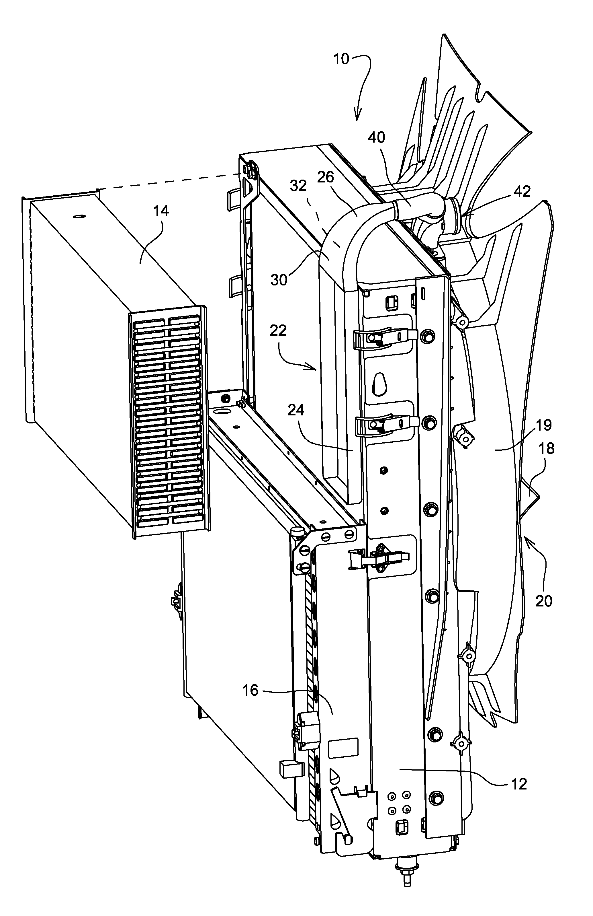
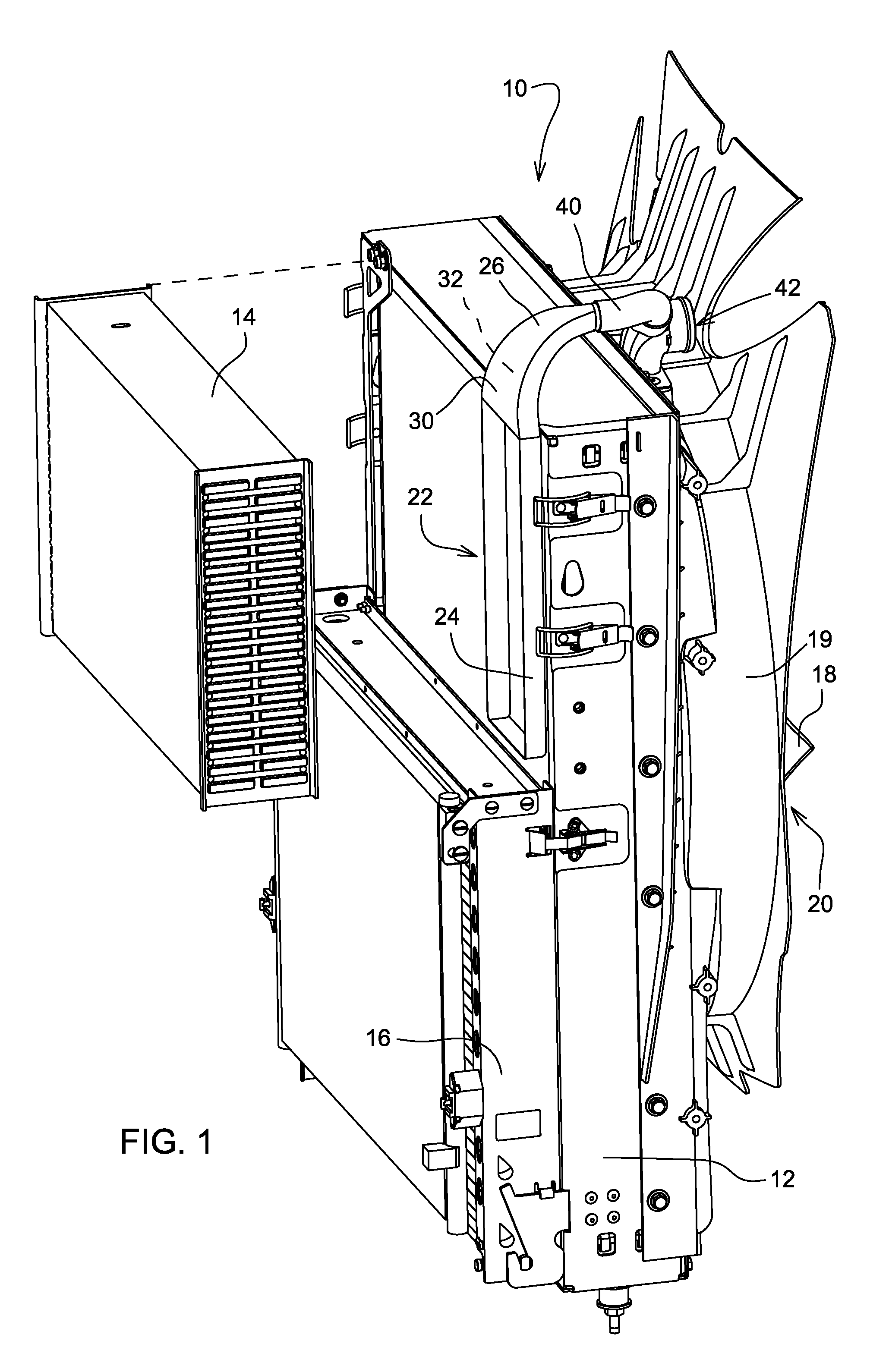
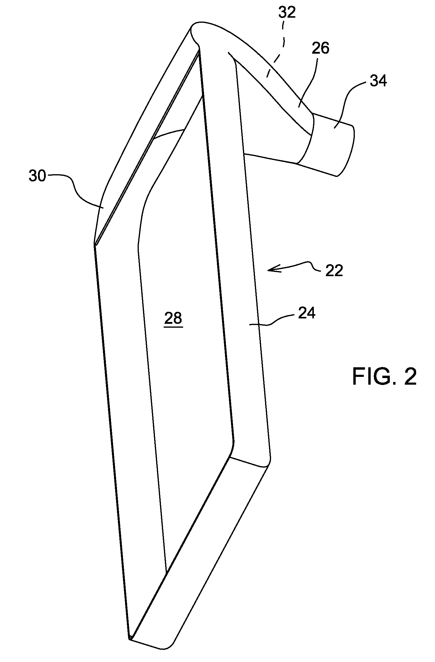
[0010]With reference to FIG. 1, a vehicle cooling system 10 includes a radiator 12, cooling units such as a charge air cooler 14 and an oil cooler 16, and a fan 18 surrounded by a fan shroud 20. The fan 18 pulls air from left to right viewing FIG. 1, through the coolers 14 and 16 and then through the radiator 12. Referring also to FIG. 5, the fan shroud 20 has an outer wall 19. Wall 19 includes an aspirator opening 49 and is attached a conventional aspirator 50. The charge air cooler 14 and the radiator 12 are dimensioned and positioned so that substantially all the air passing through the charge air cooler 14 will impinge upon the upstream side of the radiator 12. This because the charge air cooler 14 has side walls that are aligned with the side walls of the radiator 12, and the charge air cooler 14 has a top wall that which is aligned with a top wall of the radiator 12.

[0011]The cooling system 10 also includes an air diverter 22 that is attached to the cooler (14) and is non-mova...


PUM


Abstract

The invention relates to an air diverter for a vehicle cooling system. There is a need for an improved vehicle cooling system. An air diverter is provided for a vehicle cooling system having a radiator, a fan for moving air through the radiator and a cooling unit positioned in front of the radiator with respect to air moving through the radiator. The fan is surrounded by a fan shroud. The air diverter includes a collector and a conduit. The collector is positioned between the cooling unit and the radiator. The collector receives a portion of air which passes through the cooling unit. The conduit extends around an edge of the radiator and communicates air from the collector to the interior of the fan shroud while bypassing the radiator.

Description

FIELD OF THE INVENTION[0001]The present invention relates to a vehicle cooling system, and more particularly to a cooling system with an air diverter.BACKGROUND OF THE INVENTION[0002]Vehicle cooling systems are known wherein a separate cooling unit is mounted in front of the radiator. For example, a four wheel drive tractors included an air-to-air charge air cooler which was mounted in front of the radiator. Such an arrangement is also shown in U.S. Pat. No. 5,316,079 issued to Hedeen on 31 May 1994. In such an arrangement the air flowing out of the upstream cooler can be heated to a temperature which is hotter than the coolant in the downstream radiator, and this can degrade the cooling function of the downstream radiator.SUMMARY OF THE INVENTION[0003]Accordingly, an object of this invention is to improve the operation of a cooling system which has a separate cooling unit mounted in front of the radiator.[0004]This and other objects are achieved by the present invention, wherein an...

Claims


Application Information

Patent Timeline
Patent Type & Authority Patents(United States)
IPC IPC(8): B60H1/00F28D7/10F01P11/08F01P1/06F02B33/00F02B29/04
CPCF01P5/06F01P2003/185F01P2060/02
Inventor SHUTTLEWORTH, ADAM JOEOLIVER, MATTHEW ROBERTBURK, RONNIE FRANKLINGOERING, DICK J.
Owner DEERE & CO
Learn More