
Liquid ejecting apparatus and control method thereof

a liquid ejecting apparatus and control method technology, applied in the direction of printing, other printing apparatus, etc., can solve the problems of difficult to reliably suppress the cavitation generated by the negative pressure inside the liquid channel, the pressure chamber is abruptly deformed, and the printing head is ejecting errors, etc., to reduce the negative pressure, suppress the occurrence of cavitation, and reduce the effect of bubbles

Active Publication Date: 2012-09-04
SEIKO EPSON CORP
View PDF6 Cites 0 Cited by
  • Summary
  • Abstract
  • Description
  • Claims
  • Application Information

AI Technical Summary

Benefits of technology

The invention provides a liquid ejecting apparatus that can prevent ejection errors caused by bubbles and a control method for it. The apparatus includes a liquid ejecting head and a driving signal generating unit that generates an ejection driving pulse. The ejection driving pulse is a voltage waveform with multiple changing portions that change the pressure inside the pressure chamber to eject liquid from the nozzle. The apparatus can deform the pressure chamber gently when a variation in pressure is caused inside the pressure chamber, reducing the negative pressure generated inside the liquid channel and preventing ejection errors caused by bubbles. The amount of nitrogen dissolved in the liquid filled in the liquid cartridge attached to the apparatus can affect the occurrence of cavitation and ejection errors, so the control method includes adjusting the ejection driving pulse to suppress the occurrence of cavitation and ensuring a flow rate of the liquid ejected from the nozzle of 0.36 mg / s or more.

Problems solved by technology

However, if a larger variation in the pressure is applied to the pressure chamber, a negative pressure occurs when the liquid passes through a diameter-reduced portion of the liquid channels, and hence cavitation occurs due to the negative pressure, which may generate bubbles in the ink.
As a result, since a pressure loss is caused by the bubbles mixed with the ink and absorbing a variation in the pressure, so-called dot skipping may be caused when no ink is ejected from the nozzle or a flying path may be curved, thereby causing a problem that ink ejection errors occur in the printing head.
However, in the printer having a configuration in which the potential of the short driving pulse and the potential of the short idle period are changed by a switch, when a difference between the potential of the short driving pulse and the potential of the short idle period is set to be larger, the pressure chamber is abruptly deformed.
Due to the abrupt variation in the pressure chamber, it is difficult to reliably suppress the cavitation generated by the negative pressure inside the liquid channel.
As a result, the bubbles generated by the cavitation stay inside the liquid channel, and the bubbles absorb a variation in the pressure, thereby causing the problem of the ejection errors.
In this case, since the amount of nitrogen dissolved in the liquid is large, cavitation easily occurs.

Method used


Image

  • Liquid ejecting apparatus and control method thereof
  • Liquid ejecting apparatus and control method thereof
  • Liquid ejecting apparatus and control method thereof

Examples


Embodiment Construction

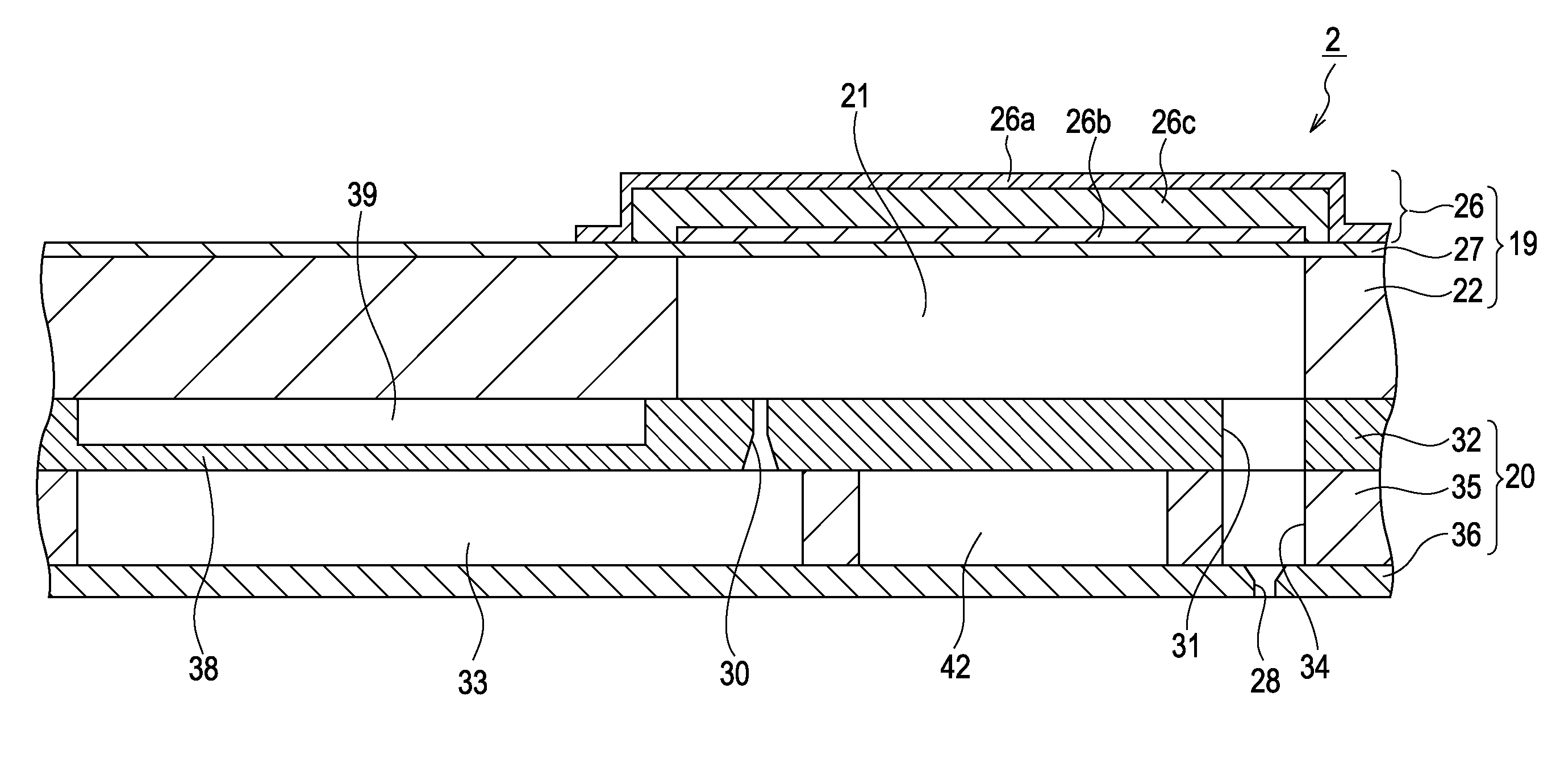
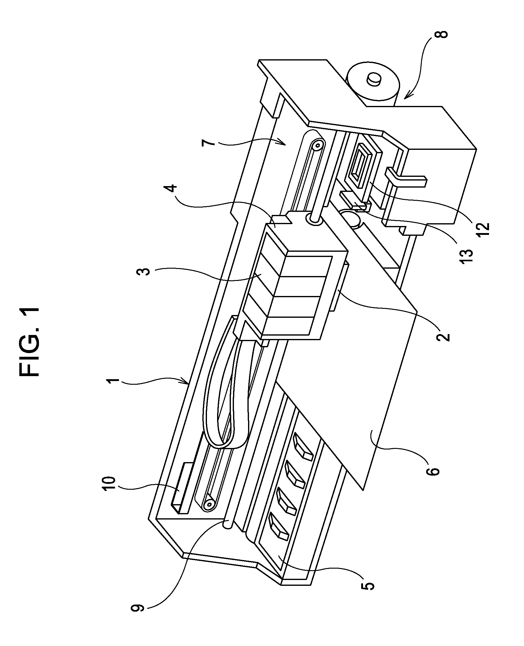
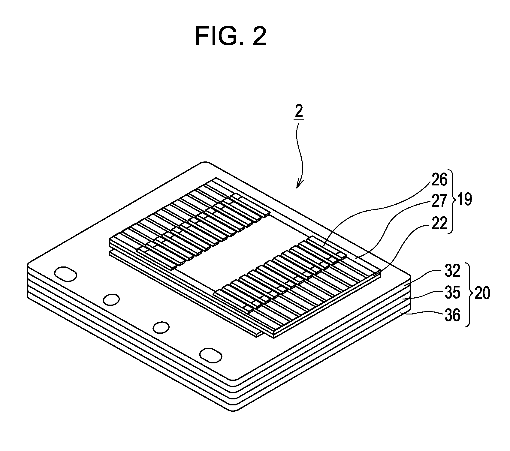
[0026]Hereinafter, exemplary embodiments of the invention will be described with reference to the accompanying drawings. In addition, in the exemplary embodiments to be described below, it should be understood that various preferred embodiments of the invention are not to be considered as limiting if there is no particular remark to limit the invention. Further, in the description below, an ink jet printing apparatus (hereinafter, simply referred to as a printer) shown in FIG. 1 is exemplified as the liquid ejecting apparatus of the invention.

[0027]A printer 1 schematically includes a carriage 4 to which a printing head 2 as a kind of liquid ejecting head is attached and to which an ink cartridge 3 (a kind of a liquid cartridge of the invention) storing ink (a kind of liquid of the invention) is detachably attached; a platen 5 which is disposed below the printing head 2; a carriage moving mechanism 7 which moves the carriage 4 mounted with the printing head 2 in the paper width dire...


PUM


Abstract

A return component that gently expands the volume of the pressure generating chamber, wherein a time interval of the expansion component is longer than that of the expansion holding component, and a time interval of the return component is longer than that of the contraction holding component, wherein a first reference potential is set to be 50% or more of the potential of the contraction holding component, and wherein when the ejection driving pulse is applied to a piezoelectric oscillator, a flow rate of the ink ejected from the nozzle opening is 0.36 mg / s or more.

Description

[0001]The entire disclosure of Japanese Patent Application No: 2009-288747, filed Dec. 21, 2009 are expressly incorporated by reference herein.BACKGROUND[0002]1. Technical Field[0003]The present invention relates to a liquid ejecting apparatus equipped with a liquid ejecting head such as an ink jet printing head, and a control method thereof.[0004]2. Related Art[0005]A liquid ejecting apparatus is an apparatus that includes a liquid ejecting head capable of ejecting a liquid and ejects various types of liquids from the liquid ejecting head. As a typical example of the liquid ejecting apparatus, for example, an image forming apparatus such as an ink jet printer (hereinafter, simply referred to as a printer) that includes an ink jet printing head (hereinafter, simply referred to as a printing head) as a liquid ejecting head and prints an image or the like by ejecting and landing a liquid-drop-shaped ink from a nozzle of the printing head onto a printing medium (ejection target) such a...

Claims


Application Information

Patent Timeline
Patent Type & Authority Patents(United States)
IPC IPC(8): B41J29/38
CPCB41J2/04573B41J2/04581B41J2/04588
Inventor KANEKO, TOMOSHIGE
Owner SEIKO EPSON CORP
Learn More