DC-DC conversion for a power amplifier using the RF input

a power amplifier and input technology, applied in the direction of amplifiers, amplifiers with semiconductor devices only, amplifiers with semiconductor devices, etc., can solve the problems of capacitors used that cannot store significant amounts of energy, waste power, and waste of available supply voltage rang

Active Publication Date: 2012-09-04
QORVO INT PTE LTD
View PDF7 Cites 61 Cited by
  • Summary
  • Abstract
  • Description
  • Claims
  • Application Information

AI Technical Summary

Benefits of technology

[0018]Yet another object of the present invention is to provide a power amplifier system where the frequency is tailored to lie at a frequency which will limit the interference of the clock on the overall output of the power amplifier.

Problems solved by technology

With a smaller swing, some of the available supply voltage range is wasted and consequently some power is wasted.
Although the charge pump requires few parts and no inductors, its main drawback is that the capacitors used are not able to store significant amounts of energy and so the load that the charge pump can drive is limited.
This is particularly the case for power amplifiers made using a CMOS process as they tend to have a more complicated structure than those made in other processes and require voltages outside the range of the power supply voltage supplied to the part.

Method used


Image

  • DC-DC conversion for a power amplifier using the RF input
  • DC-DC conversion for a power amplifier using the RF input
  • DC-DC conversion for a power amplifier using the RF input

Examples


Embodiment Construction

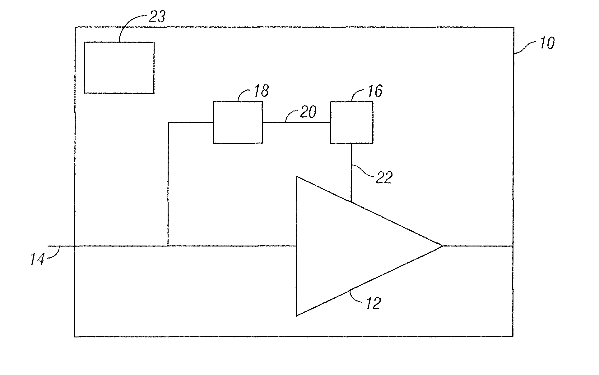
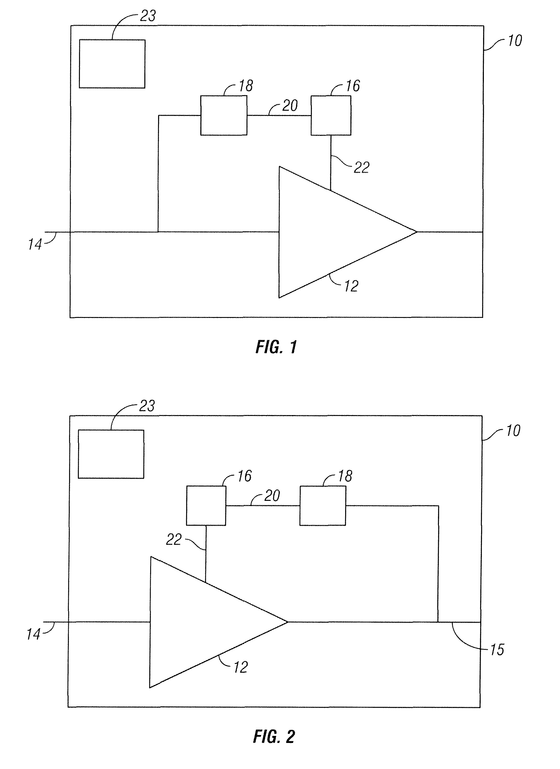
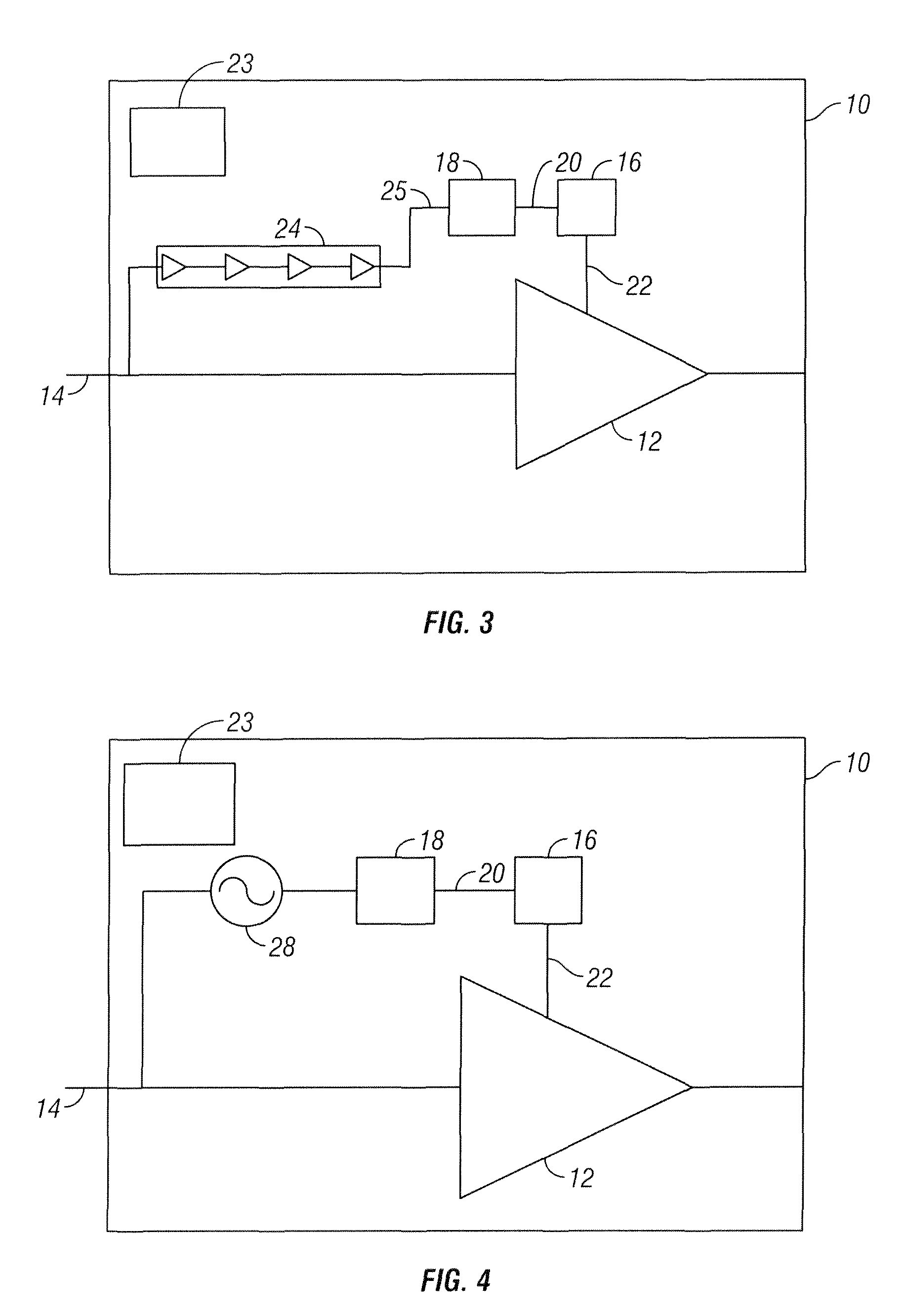
[0029]In one embodiment of the present invention, as illustrated in FIG. 1, a power amplifier system 10 includes a power amplifier 12 configured to receive an RF input 14. A DC-DC converter 16 is coupled to the power amplifier 12. Clocking circuits 18 drive the DC-DC converter 16. The clocking circuits 18 use the RF input 14 to generate a clock 20. The clock 20 acts with the DC-DC converter 16 to provide an output voltage 22 used in the power amplifier 12. The clocking circuits 18 square up the RF input to generate the clock 20. In one embodiment, the clock 20 is between high and low bands of the power amplifier 12 to minimize the clock interference of the high and low bands. A digital serial interface 23 can be included to control the clock 20. The serial interface is used to program registers which change settings in the circuits enabling us to change performance, for instance, decreasing the number of stages of division to get a higher frequency clock.

[0030]In another embodiment ...


PUM


Abstract

A power amplifier system is provided that includes a power amplifier configured to receive an RF input. A DC-DC converter is coupled to the power amplifier. Clocking circuits drive the DC-DC converter. The clocking circuits use the RF input to generate a clock. The clock acts with the DC-DC converter to provide an output voltage used in the power amplifier.

Description

CROSS-REFERENCE TO RELATED APPLICATIONS[0001]This application claims the benefit of U.S. Ser. No. 61 / 246,680 filed Sep. 29, 2009 and is related to U.S. Ser. No. 61 / 246,672, U.S. Ser. No. 61 / 246,740, U.S. Ser. No. 61 / 246,744, and U.S. Ser. No. 61 / 246,762, all filed on Sep. 29, 2009. All of the above-identified applications are fully incorporated herein by reference.BACKGROUND[0002]1. Field of the Invention[0003]This invention relates generally to power amplifiers, and more particularly to the DC-DC conversion of power amplifiers using an RF input.[0004]2. Description of the Related Art[0005]Power amplifiers are sized to deliver a certain maximum power at maximum efficiency for a nominal supply voltage (in the case of Li Ion based battery cells, this voltage is about 3.6V). The load presented to the amplifier is fixed as the load that delivers the best performance at the maximum power which means that the output swing of the amplifier makes use of all the available range of the supply...

Claims


Application Information

Patent Timeline
Patent Type & Authority Patents(United States)
IPC IPC(8): H03F3/04
CPCH03F1/0227H03F3/195H03F1/0238
Inventor SMITH, MALCOLMMOW, MATTHEW ANTHONY
Owner QORVO INT PTE LTD
Why Eureka
Try Eureka