Monitoring and operation image integrating system of plants and monitoring and operation image integrating method

a technology of operation image and monitoring system, applied in the field of monitoring or operating system, can solve the problems of heavy workload, large central control panel for monitoring or controlling (operating) the whole plant, etc., and achieve the effect of high workability and compactness

Active Publication Date: 2012-09-04
MITSUBISHI ELECTRIC CORP
View PDF21 Cites 5 Cited by
  • Summary
  • Abstract
  • Description
  • Claims
  • Application Information

AI Technical Summary

Benefits of technology

[0013]The present invention was made to solve the above-mentioned problems, and has an object of providing a monitoring and operation image integrating system of a plant in which a non-safety system and a safety system are functionally separated for obtaining safety, as well as a display image of non-safety system equipment and a display image of desired safety equipment are displayed on one monitoring and operation screen thus achieving high workability and compactness. The invention also provide a monitoring and operation image integrating method of a plant for actualizing such a plant monitoring and operation image integrating system.
[0022]According to the invention, since the non-safety system and the safety system are functionally separated for ensuring safety, as well as a monitoring and operation screen image of the safety system equipment and a monitoring and operation screen image of the non-safety system equipment are integrated and displayed as one integrated monitoring and operation screen, a compact plant monitoring and operation image integrating system or monitoring and operation image integrating method of high workability in monitoring task and operation task can be achieved. Consequently, workload on a plant operator can be reduced.

Problems solved by technology

As a result, a problem exists in a larger central control panel for monitoring or controlling (operating) the whole plant.
Moreover, a plant operator (plant manipulator) has to manipulate a large number of displays for the monitoring and operations, and thus another problem exists in heavy workload.

Method used


Image

  • Monitoring and operation image integrating system of plants and monitoring and operation image integrating method
  • Monitoring and operation image integrating system of plants and monitoring and operation image integrating method
  • Monitoring and operation image integrating system of plants and monitoring and operation image integrating method

Examples


embodiment 1

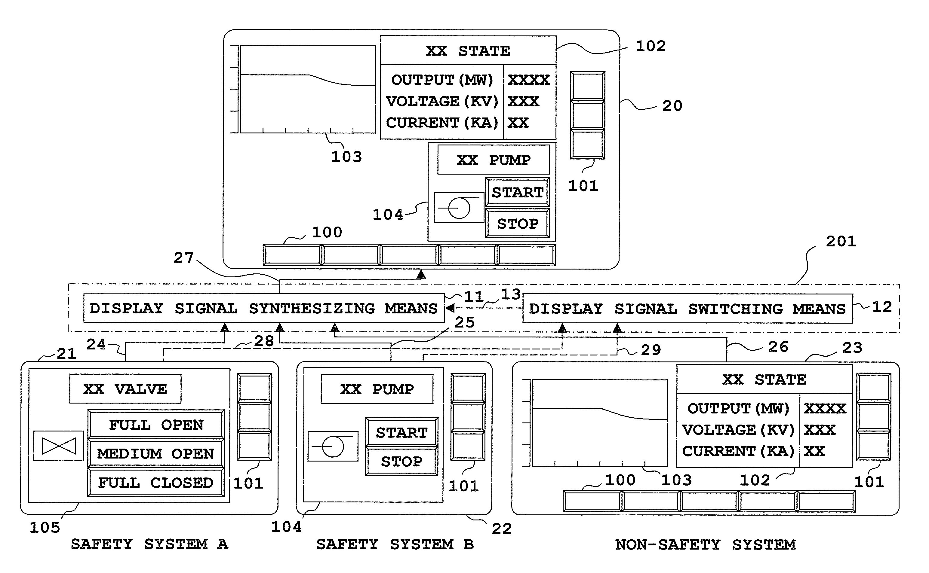
[0036]FIG. 1 is a diagram schematically illustrating an arrangement of a plant monitoring and operation image integrating system according to a first embodiment of the invention.

[0037]As illustrated in FIG. 1, a display signal synthesizer 201 is constructed of: display signal synthesizing means 11 for synthesizing a display signal (image signal) from a plurality of safety systems (for example, a safety system A and a safety system B) and a display signal (image signal) from a non-safety system equipment; and display signal switching means 12 for switching a display signal from the safety system equipment that has to be displayed based on the below-described state signal from a plurality of safety system equipments.

[0038]Furthermore, through a signal line, a display switching signal 13 is transmitted from the display signal switching means 12 to the display signal synthesizing means 11.

[0039]In addition, as mentioned above, the “safety system” refers to equipment capable of performin...

embodiment 2

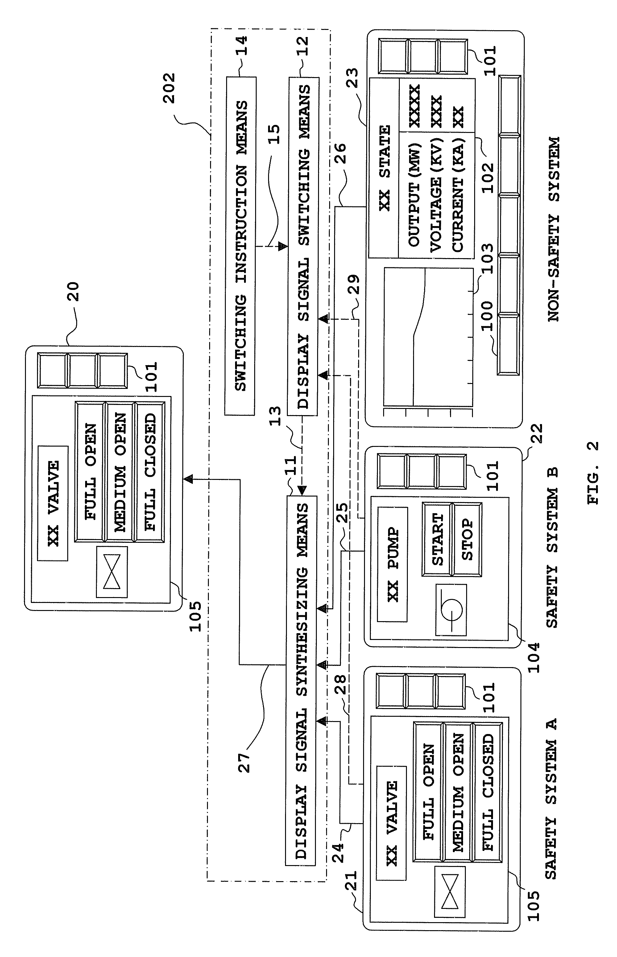
[0082]FIG. 2 is a diagram schematically illustrating an arrangement of a monitoring and operation image integrating system of a plant according to a second embodiment.

[0083]A display signal synthesizer 202 according to this second embodiment is characterized in that switching instruction means 14 is further provided in the display signal synthesizer 201 described in the foregoing first embodiment.

[0084]This switching instruction means 14, irrespective of a state signal from the plurality of safety system equipments, causes a display switching signal 13, with which a display signal from desired safety system equipment is selected, to be outputted from the display signal switching means 12 to the display signal synthesizing means 11.

[0085]The switching instruction means 14 is switching instruction means for manually indicating a display of the safety system equipment, and is executed with the use of a hardware switch.

[0086]Furthermore, a switching instruction signal 15 is outputted fr...

embodiment 3

[0096]FIG. 3 is a diagram schematically illustrating an arrangement of a monitoring and operation image integrating system of a plant according to a third embodiment.

[0097]A display signal synthesizer 203 according to this third embodiment is characterized in that operation signal sorting means 16 is further provided in the display signal synthesizer 201 described in the foregoing first embodiment.

[0098]In the drawing, reference numeral 17 is a signal for obtaining information about from which safety system equipment a display signal is synthesized.

[0099]Furthermore, reference numeral 30 designates an operating position signal on the integrated monitoring and operation screen 20, numeral 31 designates an operating position signal to be inputted to the non-safety system, numeral 32 designates an operating position signal to be inputted to the safety system B, and numeral 33 designates an operating position signal to be inputted to the safety system A.

[0100]In addition, although a sig...


PUM


Abstract

A monitoring and operation image integrating system include: a display signal synthesizing unit to which a display signal from a plurality of safety equipments and that from non-safety equipment are inputted, and which synthesizes a display signal from the plural safety equipments and a display signal from the non-safety equipment; display signal switching unit to which a state signal showing an operation state of whether or not each monitoring and operation screen image of the plural safety equipments displays an operating device of the equipment, is inputted, and which switches a display signal from a safety equipment to be synthesized by the display signal synthesizing unit based on the inputted state signals; and an integrated monitoring and operation screen display that displays a display signal synthesized by the display signal synthesizing unit as an integrated monitoring and operation screen of a plant.

Description

BACKGROUND OF THE INVENTION[0001]1. Field of the Invention[0002]The present invention relates to systems for monitoring or operating plants that includes safety system equipment and non-safety system equipment with the use of images and, more particularly, to a monitoring and operation image integrating system of plants such as nuclear power plants that requires to have a high safety.[0003]2. Description of the Related Art[0004]In conventional plant monitoring and operation systems, to ensure safety of plants, separation is established between safety system equipment and non-safety system equipment, or monitoring function is separate from operating function.[0005]From the viewpoint of such functional separation, an operation screen and monitoring screen of a system is separated, or a monitoring and operation screen of a safety system and a monitoring and operation screen of a non-safety system are physically separated.[0006]In addition, the “safety system” refers to equipment capabl...

Claims


Application Information

Patent Timeline
Patent Type & Authority Patents(United States)
IPC IPC(8): G06K9/00H04N7/18
CPCG05B23/0267G21C17/00G21D3/008G21Y2002/208G21Y2002/301G21Y2002/304G21Y2004/30G21Y2004/40Y02E30/39Y02E30/00Y02E30/30
Inventor KITAMURA, MASASHIOHI, TADASHI
Owner MITSUBISHI ELECTRIC CORP
Why Eureka
Try Eureka