
Systems and methods for employing multiple filters to detect T-wave oversensing and to improve tachyarrhythmia detection within an implantable medical device

a technology of tachyarrhythmia detection and multiple filters, applied in the field of implantable medical devices, can solve the problems of ventricular fibrillation, fatality, and difficulty in obtaining an accurate measurement if not terminated, and achieve the effect of improving the accuracy of the ventricular rate measuremen

Active Publication Date: 2012-09-04
PACESETTER INC
View PDF15 Cites 14 Cited by
  • Summary
  • Abstract
  • Description
  • Claims
  • Application Information

AI Technical Summary

Benefits of technology

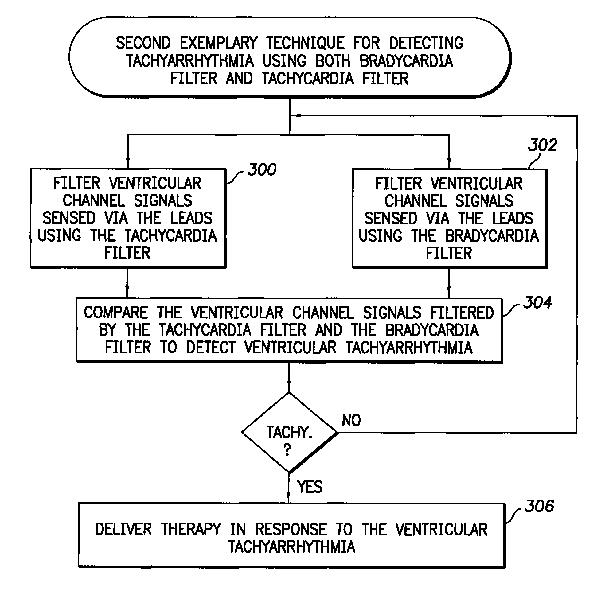
[0016]In a first illustrative example of the first general embodiment of the invention, tachyarrhythmia is detected using signals filtered by the bradycardia filter in combination with signals filtered by the tachycardia filter by: detecting a preliminary indication of tachyarrhythmia using signals filtered by the bradycardia filter; and, in response, confirming the detection of tachyarrhythmia using signals filtered by the tachycardia filter. That is, the bradycardia filter, which is traditionally used only to detect bradycardia, is additionally used to detect a preliminary indication of a tachyarrhythmia, such as VT. If such a preliminary indication is detected, the tachycardia filter is then activated to confirm the detection of the tachyarrhythmia, before therapy is delivered. In this manner, the tachycardia filter need not run continuously, but is instead activated only when there is some indication of possible tachyarrhythmia, and hence power is saved. In one specific example, a single filter is employed that is capable of being programmed to operate as either a bradycardia filter or a tachycardia filter. By default, it operates as a bradycardia filter. If an indication of tachyarrhythmia is detected, it is then reprogrammed to instead operate as a tachycardia filter. In this manner, a single reconfigurable filter can be used to perform the functions of both bradycardia filtering and tachycardia filtering, thus saving device resources.
[0022]Thus, with this implementation, by simultaneously using both a bradycardia and a tachycardia filter and comparing the two filtered signals to one another, very prompt detection of VT can be achieved, while also detecting possible T-wave oversensing.

Problems solved by technology

However, some tachycardias, particularly ventricular tachycardia, can trigger ventricular fibrillation (VF) wherein the heart beats chaotically such that there is little or no net flow of blood from the heart to the brain and other organs.
VF, if not terminated, is fatal.
Accordingly, it can be difficult to obtain an accurate measure of the ventricular rate from the wideband-filtered signals and so it can be difficult to reliably detect either bradycardia or tachycardia from the wideband-filtered signals.
As can be appreciated, T-wave oversensing is a significant concern since misidentification of T-waves as R-waves can result in significant miscalculation of the true heart rate within the patient, causing therapy to be delivered when not warranted or potentially causing therapy to be withheld even when needed.
Insofar as bradycardia is concerned, T-wave oversensing might result in a failure to detect bradycardia since misidentification of T-waves as R-waves would result in a significantly higher heart rate being detected than actually occurring within the patient.
This is due to the fact that the frequencies associated with the V-fib waves of interest are also associated with T-waves, and hence the filter cannot eliminate all T-waves while still retaining the V-fib waves.
This is difficult, at best, since the relative magnitudes of the R-waves, V-fib waves and T-waves may change significantly over time within the patient, perhaps due to the use of medications or due to physiological or anatomical changes in the heart brought on by medical conditions, such as cardiac ischemia, myocardial infarctions, congestive heart failure, etc.
Hence, T-wave oversensing is a significant problem within the tachycardia-filtered signals.
That is, T-wave oversensing might occur.
Without complete elimination of the T-wave, the ventricular rate cannot be accurately and reliably measured based solely on the output of the tachycardia filter (at least at the rates associated with VT / VF), and hence problems arise in the detection of VT / VF or other forms of ventricular tachyarrhythmia.
Failure to properly detect VT / VF when it is present can result in a failure to deliver appropriate therapy.
False detection of VT / VF when it is not present can result in delivery of inappropriate therapy.

Method used


Image

  • Systems and methods for employing multiple filters to detect T-wave oversensing and to improve tachyarrhythmia detection within an implantable medical device
  • Systems and methods for employing multiple filters to detect T-wave oversensing and to improve tachyarrhythmia detection within an implantable medical device
  • Systems and methods for employing multiple filters to detect T-wave oversensing and to improve tachyarrhythmia detection within an implantable medical device

Examples


first embodiment

[0136]FIG. 26 illustrates, in block diagram form, pertinent components of the ventricular sense amplifier 1184 and the combined bradycardia filter / tachycardia filter-based oversensing detection system 1203 of FIG. 24, and particular illustrating pertinent sub-components thereof. As before, the ventricular sense amplifier 1184 includes the bradycardia filter 1207, the tachycardia filter 1209 and the wideband filter 1211. The combined bradycardia filter / tachycardia filter-based oversensing detection system 1203 includes various components directed to the various illustrative embodiments described above. It should again be understood that the typical combined bradycardia filter / tachycardia filter-based oversensing detection system will not include each of the components but may be equipped, for example, with only one of the set of components corresponding to whichever particular embodiment is implanted. Briefly, the oversensing detection system may include first embodiment components i...

second embodiment

[0137]The oversensing detection system may additionally or alternatively include second embodiment components including a detection unit 1233 operative, upon detection of a first ventricular event either in signals filtered by the bradycardia filter or in signals filtered by the tachycardia filter, to determine whether a second ventricular event is detected in the signals filtered by the tachycardia filter within a predetermined time window following the first event; and an identification unit 1235 operative, if a second ventricular event is detected within the predetermined time window, to identify the second event as being a false ventricular depolarization event indicative of tachycardia-filter oversensing, and operative, if a second ventricular event is not detected within the predetermined time window, to identify the second event as being indicative of a true ventricular depolarization event, generally in accordance with the techniques of FIG. 21, discussed above.

third embodiment

[0138]The oversensing detection system may additionally or alternatively include third embodiment components including an identification unit 1237 operative to identify possible ventricular depolarization events within signals filtered, respectively, by the wideband filter, the bradycardia filter, and the tachycardia filter, and a comparison unit 1239 operative to compare the timing of the possible ventricular depolarization events identified within the respective filtered signals to identify oversensed ventricular repolarization events, generally in accordance with the techniques of FIG. 22, discussed above.


PUM


Abstract

Techniques for detecting tachyarrhythmia and also for preventing T-wave oversensing use signals filtered by a narrowband bradycardia filter in combination with signals filtered by a narrowband tachycardia filter. A separate wideband filter may also be used.

Description

RELATED APPLICATIONS[0001]This application is related to U.S. patent application Ser. No. 11 / 776,266, filed Jul. 11, 2007 entitled “SYSTEMS AND METHODS FOR EMPLOYING MULTIPLE FILTERS TO DETECT T-WAVE OVERSENSING AND TO IMPROVE TACHYARRHYTHMIA DETECTION WITHIN AN IMPLANTABLE MEDICAL DEVICE” which is fully incorporated by reference herein.FIELD OF THE INVENTION[0002]The invention generally relates to implantable medical devices such as pacemakers and implantable cardioverter / defibrillators (ICDs) and, in particular, to (1) techniques for detecting ventricular tachyarrhythmia and also to (2) techniques for preventing T-wave oversensing.BACKGROUND OF THE INVENTION[0003]An arrhythmia is an abnormal heart beat pattern. One example of arrhythmia is bradycardia wherein the heart beats at an abnormally slow rate or wherein significant pauses occur between consecutive beats. Other examples of arrhythmia include tachyarrhythmias wherein the heart beats at an abnormally fast rate. With an atria...

Claims


Application Information

Patent Timeline
Patent Type & Authority Patents(United States)
IPC IPC(8): A61B5/0452A61B5/0456A61B5/352
CPCA61B5/0456A61B5/0464A61N1/3702A61N1/395A61B5/725A61B5/352A61B5/363
Inventor BHARMI, RUPINDERSNELL, JEFFERY D.BORNZIN, GENE A.FLORIO, JOSEPH J.BOILEAU, PETER
Owner PACESETTER INC
Learn More