
Object and vehicle detection and tracking using 3-D laser rangefinder

a laser rangefinder and object technology, applied in the field of object detection methods and systems, can solve the problems of unable to distinguish between objects in cluttered environments, unable to determine the height of objects, and unable to detect objects reliably

Active Publication Date: 2012-09-04
GM GLOBAL TECH OPERATIONS LLC
View PDF17 Cites 45 Cited by
  • Summary
  • Abstract
  • Description
  • Claims
  • Application Information

AI Technical Summary

Benefits of technology

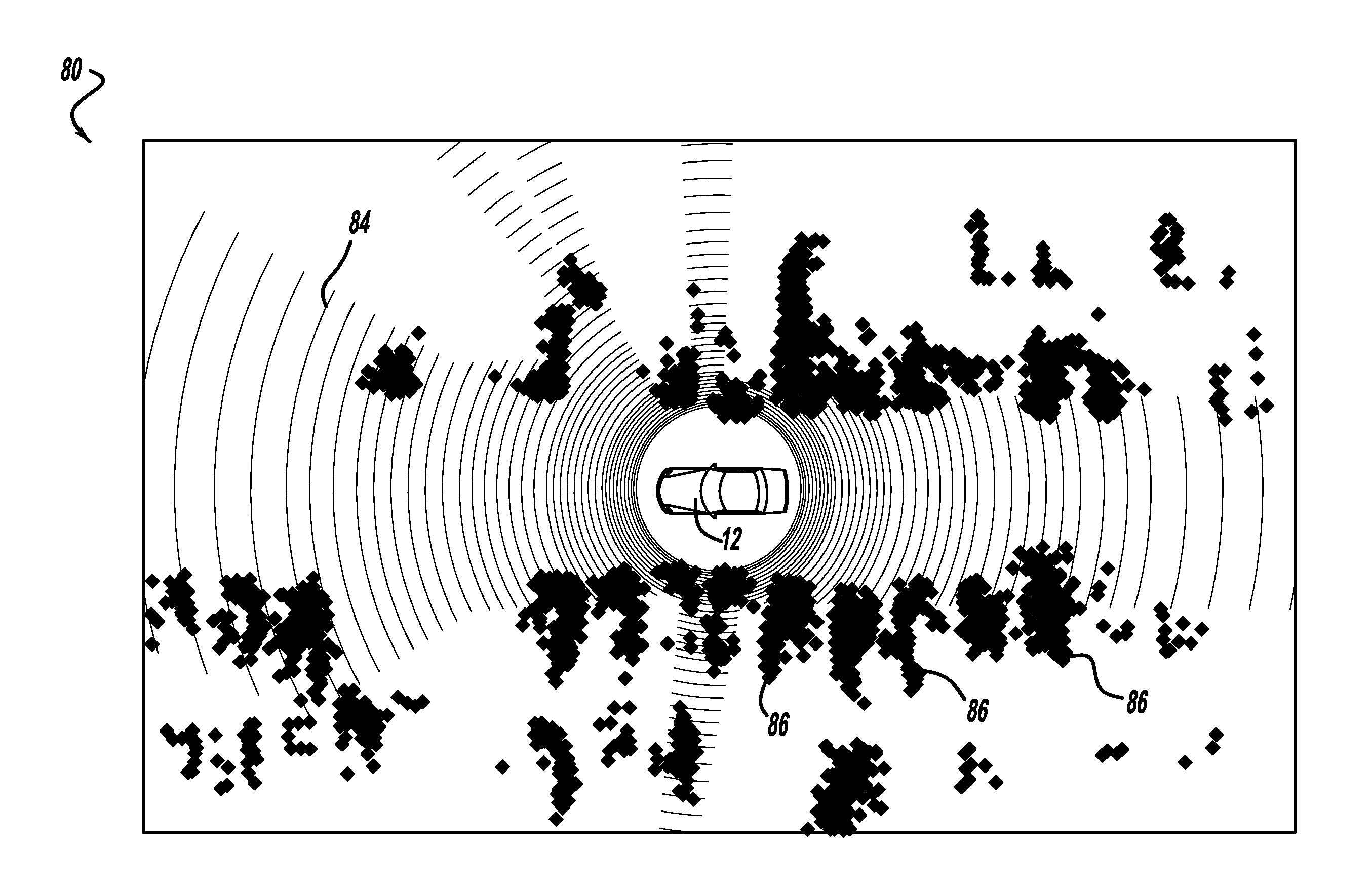
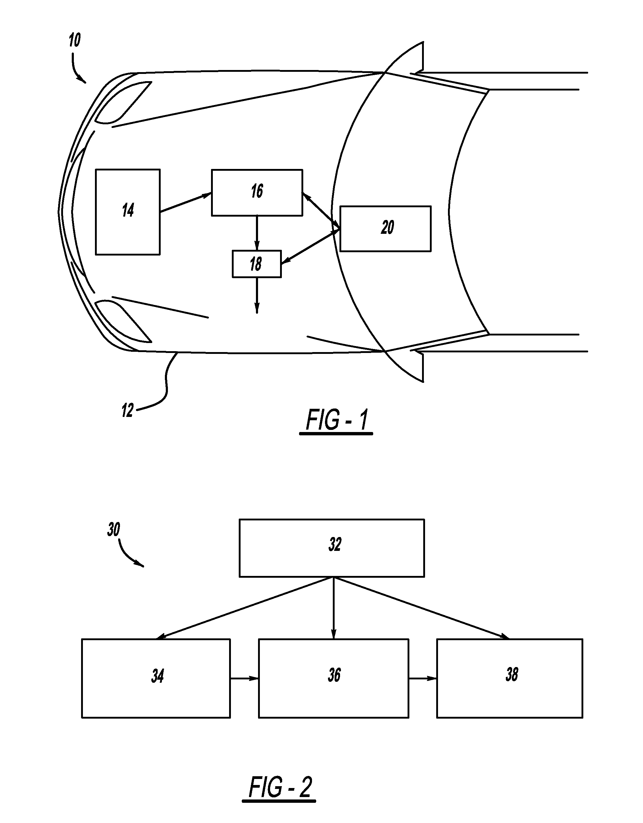
The present invention is a method and system for detecting and tracking objects near a vehicle using a three-dimensional laser rangefinder. The system can estimate the location of a ground plane and construct a non-flat, segmented ground surface based on point cloud data. It can also detect and track dynamic objects, such as other vehicles, pedestrians, and animals, and output the data on their size, shape, range, and velocity relative to the ground and the host vehicle. This output data can be used by downstream applications, such as collision avoidance or semi-autonomous driving systems.

Problems solved by technology

However, object detection systems known in the art and available on the market have limitations in terms of how well they can detect and track objects, and how reliably the object data can be used for vehicle control purposes.
These systems often have problems distinguishing between objects in cluttered environments typically found in realistic driving situations.
They may be able to detect the two dimensional shape of an object, but not be able to determine the object's height, thus unable to determine if the object is actually a feature of the ground or road surface.
Or they may be able to detect the presence of objects, but unable to distinguish between closely spaced objects based on relative velocity or three dimensional characteristics.
Finally, existing radar or camera-based object detection systems may completely fail to detect some objects, due to a lack of reflectivity or lack of color differentiation of the objects.

Method used


Image

  • Object and vehicle detection and tracking using 3-D laser rangefinder
  • Object and vehicle detection and tracking using 3-D laser rangefinder
  • Object and vehicle detection and tracking using 3-D laser rangefinder

Examples


Embodiment Construction

[0018]The following discussion of the embodiments of the invention directed to a method and system for object detection and tracking using a three dimensional laser rangefinder is merely exemplary in nature, and is in no way intended to limit the invention or its applications or uses.

[0019]Vehicle collision avoidance and semi-autonomous driving systems require very accurate information about objects in their surrounding environment in order to be effective. Traditional object detection systems using radar or camera-based vision technology can have problems discerning objects in the cluttered environment that is typical of real-world driving situations. For example, radar-based systems may not reliably detect non-metallic objects, such as concrete curbs, rocks, and vegetation. And camera-based vision systems can have difficulty discerning between objects of similar color or brightness, and cannot directly measure range or distance to an object. In the present invention, a three dimen...


PUM


Abstract

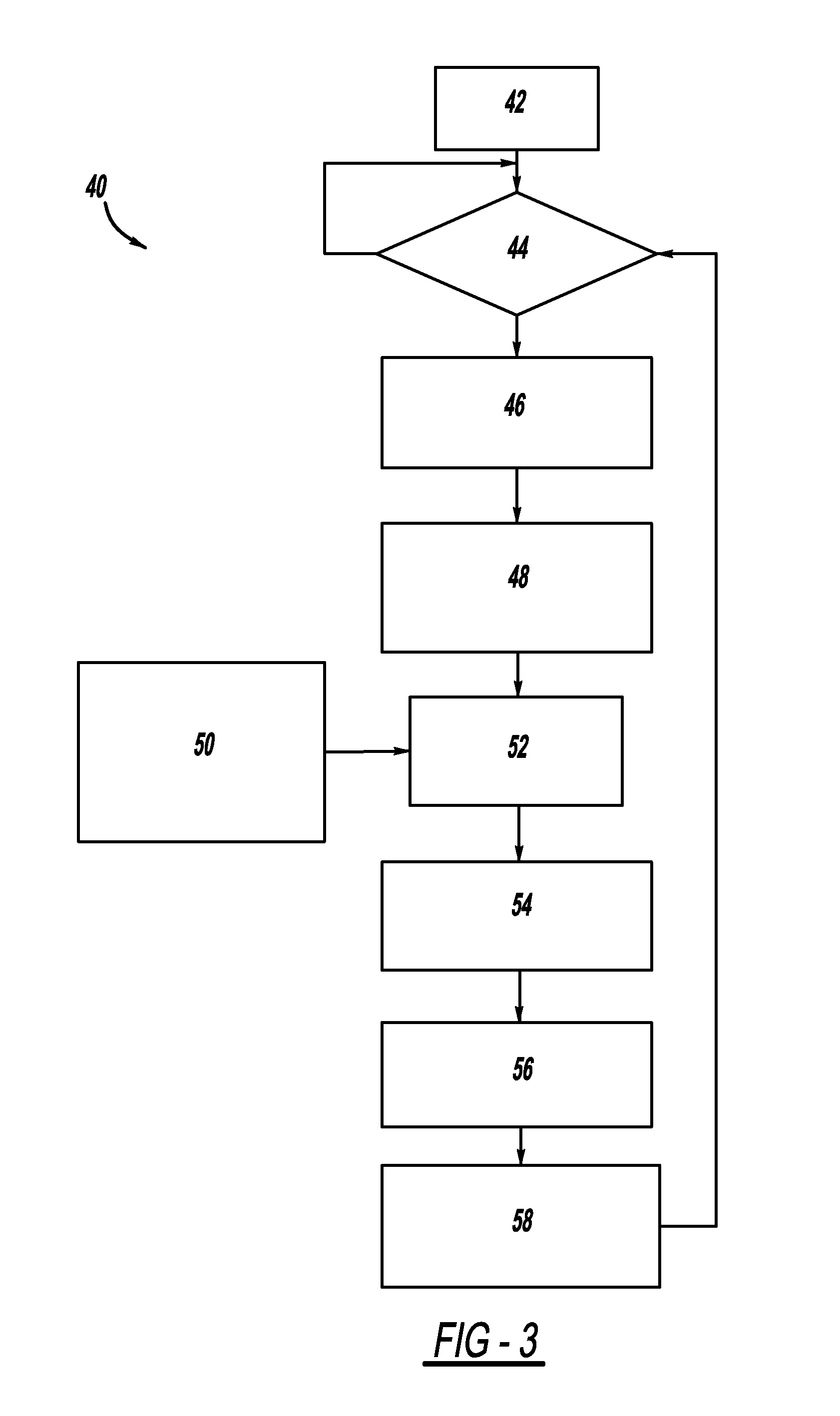
A method and system for detecting and tracking objects near a vehicle using a three dimensional laser rangefinder. The method receives points from the laser rangefinder, where the points represent locations in space where the rangefinder senses that some object exists. An algorithm first estimates the location of a ground plane, based on a previous ground plane location, data from onboard sensors, and an eigenvector calculation applied to the point data. Next, a plan view occupancy map and elevation map are computed for stationary objects, based on point data in relation to the ground plane. Finally, dynamic objects are detected and tracked, sensing objects which are moving, such as other vehicles, pedestrians, and animals. The output of the method is a set of stationary and dynamic objects, including their shape, range, and velocity. This output can be used by downstream applications, such as collision avoidance or semi-autonomous driving systems.

Description

BACKGROUND OF THE INVENTION[0001]1. Field of the Invention[0002]This invention relates generally to an object detection method and system and, more particularly, to an object detection method and system for a vehicle which uses a three dimensional laser rangefinder to detect and track both stationary and moving objects in the vicinity of the vehicle, providing a source of input for downstream vehicle control applications.[0003]2. Discussion of the Related Art[0004]Many modern vehicles include a variety of sophisticated electronic systems for safety and navigation assistance. In some vehicles, these systems include object detection and adaptive cruise control systems, which can alert a driver to an obstacle near the vehicle, or even control the vehicle's brakes or steering to maintain a safe distance to another vehicle or object. However, object detection systems known in the art and available on the market have limitations in terms of how well they can detect and track objects, and ...

Claims


Application Information

Patent Timeline
Patent Type & Authority Patents(United States)
IPC IPC(8): G06F17/10
CPCG01S17/936G01S7/4808G01S17/42G01S17/89B60W30/0956G08G1/165G08G1/166G01S17/931
Inventor ZENG, SHUQING
Owner GM GLOBAL TECH OPERATIONS LLC
Learn More