Vibration damper for a drive train

a drive train and damper technology, applied in the direction of vibration suppression adjustment, spring/damper, yielding coupling, etc., can solve the problems of high demands on the stability of the elastic disk, unsatisfactory heat development, and high construction costs, so as to reduce the number of interruptions in the shaft, reduce the number of interruptions, and improve the effect of synchronous operation

Active Publication Date: 2012-09-11
NEUMAYER TEKFOR ENG GMBH
View PDF34 Cites 3 Cited by
  • Summary
  • Abstract
  • Description
  • Claims
  • Application Information

AI Technical Summary

Benefits of technology

[0032]In one embodiment of the vibration damper of the invention, the damping part comprises, at least on a front side thereof, an axially elastic damping washer. As a result of the arrangement of the elastic damping part radially between the two shaft parts with an axial length for transmitting torque, it is possible to dispense with flanges, which have a radial diameter that is many times the shaft diameter and between which the elastic damping part is disposed. Since the axial extension of a shaft is given anyway in most applications and therefore not relevant to the installation space, it is possible to save installation space in the radial direction by using the proposed vibration damper of the invention which only marginally expands the shaft diameter. As a result of the improved guidance of the two shaft parts relative to each other, flexing is avoided so that there is reduced development of heat, and therefore higher efficiency is achieved. The vibration damper also has the advantage, for example, that it makes do with less installation space.
[0033]A high degree of synchronous operation and balancing quality is achieved by means of the so-called tube-in-tube arrangement of the shaft parts with the damping part. The parts are self-centering on each other so that it is possible to dispense with a centering operation when mounting the shaft parts on each other.
[0037]By using variably elastic materials, there preferably results a surface pressure between the rotary drivers and the harder material on the one hand and a surface pressure between the harder material and the more elastic material on the other. The surface ratios between the rotary drivers and the negative profiles are configured to be appropriately smaller than the surface ratios of the different materials of the damping part so that a lesser surface pressure is achieved on the elastic material by means of the selection and arrangement of the different materials, while higher surface pressure and therefore smaller contact surfaces can be achieved by the use of a more rigid material for torque transmission from the shaft parts into the damping part.
[0040]The combination of the vibration damper with a constant velocity joint has proved particularly advantageous. In this case, the constant velocity joint is mounted on the first or the second shaft part, for example, so as to be rotationally fixed in that it is mounted on the damper in a rotationally fixed manner, for example, by means of corresponding profiling, for example, on the rotary drivers already provided for acting upon the damping part, and is fixed axially, for example, crimped against an axial stop. In doing so, it can be advantageous if the preferably lubricated constant velocity joint is encapsulated relative to the damping part. Among other things, a sealing washer can be disposed between the constant velocity joint and the damping part in this connection. Advantageously, the sealing washer can also be made of a base part of the sleeve so that there is no requirement of any additional parts. The use of a constant velocity joint in the vibration damper enables large articulation angles to be maintained permanently in the shaft without damage to the damping part. Furthermore, a very good synchronous operation is achieved even at larger articulation angles. Similarly, it is possible to provide not only fixed ball joints but also constant velocity joints comprising slip joints and / or displacement units in the form of roller compensators.
[0041]According to a further advantageous illustrative embodiment, the vibration damper can additionally exhibit an axial damping effect in that the damping part is fixed or braced axially between the two shaft parts. In this case, the damping part may comprise axially elastic portions. These portions can be provided, in sandwich architecture, on one or both end faces and / or in between in that the damping part is divided into two or more sections or appropriately elastic regions are provided in the same. Alternatively or additionally, the damping part can be provided, on its end faces or in between, with one or more axially elastic damping washers that are acted upon in the case of axial loads by corresponding axial end faces of the shaft parts. The axial damping travel can be limited in that the shaft parts collide with each other in order to protect the axially elastically effective regions of the damping part from damage in the case of extreme stresses.
[0042]The invention also relates to a drive shaft that can be used in the form of a propeller shaft and / or a side shaft, for example, in a drive train of a motor vehicle, the drive shaft comprising rotationally locked end regions for achieving a rotationally locked connection of the drive shaft to additional connecting pieces of the drive train such as transmission output shafts, differential input or output shafts, wheel hubs and the like, and the vibration damper described above being disposed between the same. Within the scope of the invention, it is possible to provide an axial length compensation of the drive shaft at a distance from the vibration damper in the axial direction, which length compensation is in the form of, for example, a displacement unit comprising inner teeth disposed on a shaft section, an additional shaft section comprising outer teeth, and rolling elements disposed radially between the same. In one embodiment, a component of the displacement unit forms a structural unit with the vibration damper. In particular, the vibration damper in an additional embodiment comprises longitudinal teeth for the axial length compensation. In doing so, it has proved advantageous if the displacement unit or at least a component of the same is provided in the form of a structural unit with the vibration damper in that, for example, the outer teeth or preferably the inner teeth are provided on a shaft part of the vibration damper so that the number of shaft components can be reduced, for example, to three and the number of interruptions in the shaft can be minimized in favor of achieving a stability of the shaft.

Problems solved by technology

The high surface pressure at the transition points between the flange parts and the elastic disk and the resulting flexing leads to an undesirable heat development and high demands on the stability of the elastic disk.
This construction is very elaborate and cost-intensive.
The disadvantage of this known arrangement is that the damping characteristics of the solid and homogenously constructed damping parts are solely determined by the properties of the material used for the damping part.

Method used


Image

  • Vibration damper for a drive train
  • Vibration damper for a drive train
  • Vibration damper for a drive train

Examples


Embodiment Construction

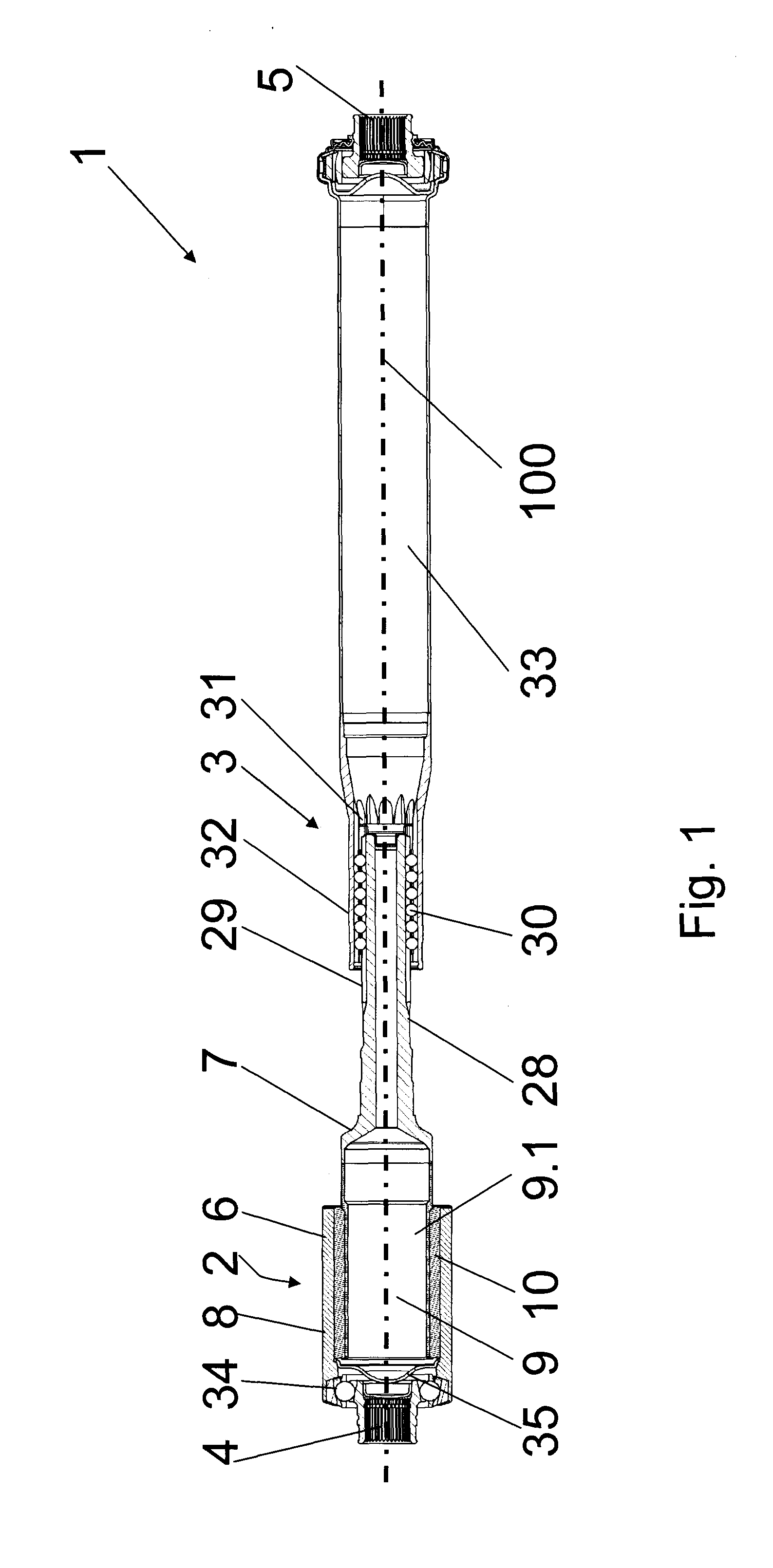
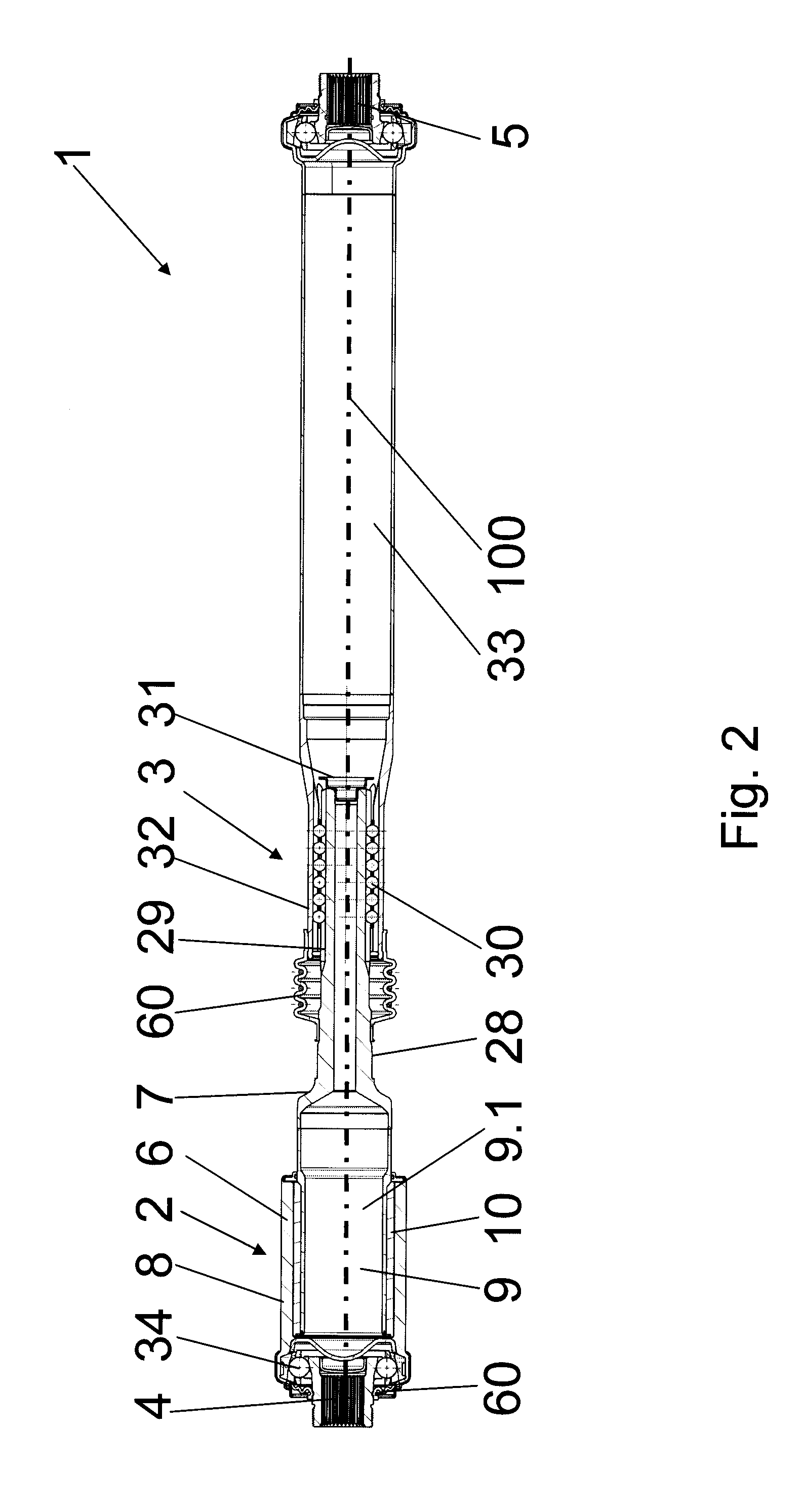
[0057]FIG. 1 shows a drive shaft 1 comprising a vibration damper 2 and a linear displacement unit 3, and the rotation or longitudinal axis 100. The ends of the drive shaft 1 comprise connecting parts 4, 5, which are in the form of inner teeth and which enable a rotationally locked connection of the drive shaft to additional connecting pieces (not shown) such as wheel hubs or a differential gear on the one hand and inboard-mounted parts such as a transmission output shaft on the other.

[0058]The vibration damper 2 is integrated into the drive shaft 1 by means of the first and second shaft parts 6, 7. The first shaft part 6 is in the form of a sleeve 8, into which the inner part 9—or more particularly, the end region 9.1 of the inner part 9—of the second shaft part 7 is inserted axially. The damping part 10 is disposed radially between the sleeve 8 and the inner part 9, which damping part 10 is configured to be elastic or contains elastic elements. The sleeve 8 and the inner part 9 com...


PUM


Abstract

A vibration damper (2) that is effective in the direction of rotation of a drive shaft and has a small radial extension. For this purpose, a first shaft part (6) is provided as a sleeve (8) and a second shaft part (7) is provided as an inner part extending axially into the sleeve (8). The two shaft parts (6, 7) engage via rotary drivers in complementary negative profiles (15, 16) of an interposed elastic damper part (10) in the direction of rotation. In addition to the negative profiles, the damper part may be provided with recesses (40) which modify its damping characteristics.

Description

CROSS REFERENCE TO RELATED APPLICATIONS[0001]This application is a continuation of international patent application no. PCT / DE2010 / 000261, filed Mar. 12, 2010, designating the United States of America and published in German on Sep. 16, 2010 as WO 2010 / 102611, the entire disclosure of which is incorporated herein by reference. Priority is claimed based on Federal Republic of Germany patent application nos. DE 10 2009 013 082.9, filed Mar. 13, 2009, and DE 10 2009 057 914.1, filed Dec. 11, 2009, the entire disclosures of which are likewise incorporated herein by reference.BACKGROUND OF THE INVENTION[0002]The invention relates to a vibration damper for a shaft of a drive train, which shaft comprises a first shaft part and a second shaft part and an elastically deformable damping part, which is disposed between the shaft parts and which is acted upon by each of the two shaft parts in a rotationally locked manner, the first shaft part comprising a sleeve comprising radially inwardly ori...

Claims


Application Information

Patent Timeline
Patent Type & Authority Patents(United States)
IPC IPC(8): F16D3/76
CPCF16F15/1245F16D3/68
Inventor LEHMANN, MARTIN
Owner NEUMAYER TEKFOR ENG GMBH
Why Eureka
Try Eureka