Method and system for receiver synchronization

a receiver and receiver technology, applied in the field of digital video broadcasting, can solve the problems of difficult to achieve the performance of fine frequency offset estimation is not accommodated in the time domain component of these traditional techniques, and the difficulty of achieving fine synchronization in the time domain, which is difficult without the use of continuous pilots

Active Publication Date: 2012-09-11
AVAGO TECH INT SALES PTE LTD
View PDF5 Cites 7 Cited by
  • Summary
  • Abstract
  • Description
  • Claims
  • Application Information

AI Technical Summary

Benefits of technology

[0027]However, tracking the location of scattered pilots for use in phase error correction can be problematic. That is, scattered pilots are not located in the same carrier index in each symbol. Therefore, to use scattered pilots as a substitute for continuous pilots for phase error correction, one needs to know the actual scattered pilot symbol index or, alternatively, wait for a complete cycle of scattered pilots. The present invention provides an approach to resolving this issue by substituting a Gold sequence, with good autocorrelation properties, in the place of the traditional pseudorandom sequence. Use of the Gold sequence enables synchronization to be achieved completely in the time domain.

Problems solved by technology

The time domain component of these traditional techniques does not accommodate the performance of fine frequency offset estimation.
Performing fine synchronization in time domain, however, is not so easily accomplished.
Achieving fine synchronization in the time domain, however, is difficult without the use of the continuous pilots.
However, for multicarrier systems that use multiple sized FFTs (such as DVB-T2), using pseudorandom sequences in this manner would add extra complexity to the receiver due to the need to receive and process multiple sequences of different sizes.

Method used


Image

  • Method and system for receiver synchronization
  • Method and system for receiver synchronization
  • Method and system for receiver synchronization

Examples


Embodiment Construction

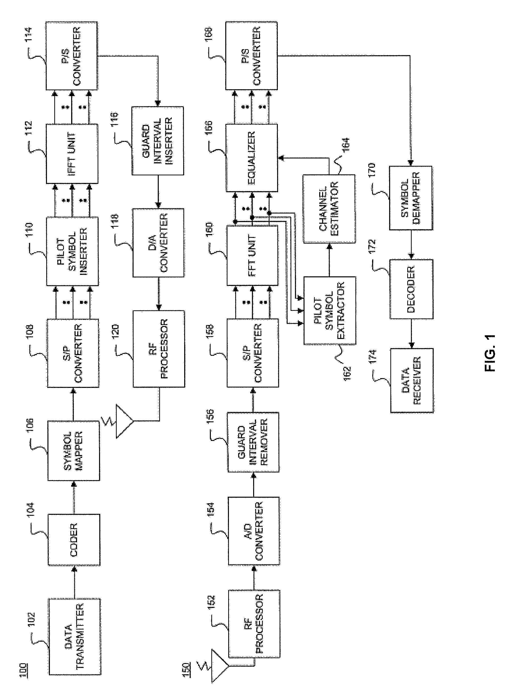
[0025]Consistent with the principles of the present invention as embodied and broadly described herein, the present invention includes a method for synchronizing a multiple carrier receiver to receive a transmitted signal. The method includes determining a location of one or more scattered pilot carriers in a received symbol sequence and modulating the scattered pilot carriers in accordance with a single pseudorandom binary sequence. The method also includes performing phase error correction via the modulated scattered pilot carriers.

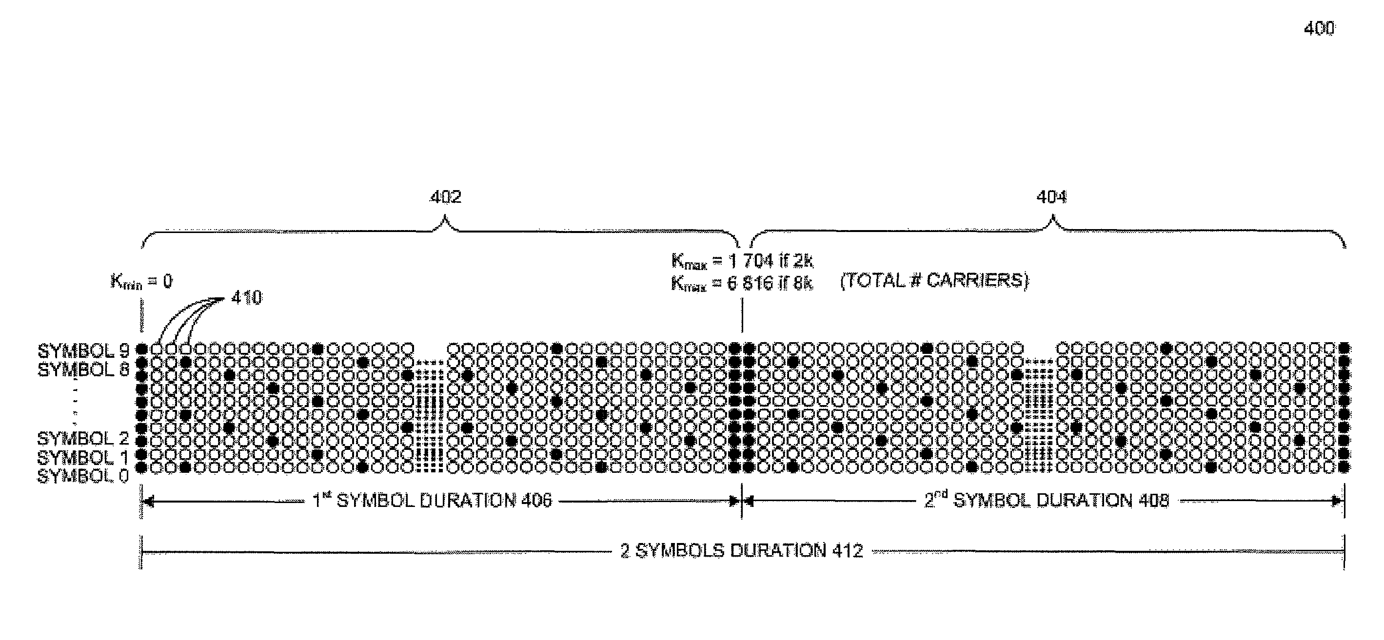
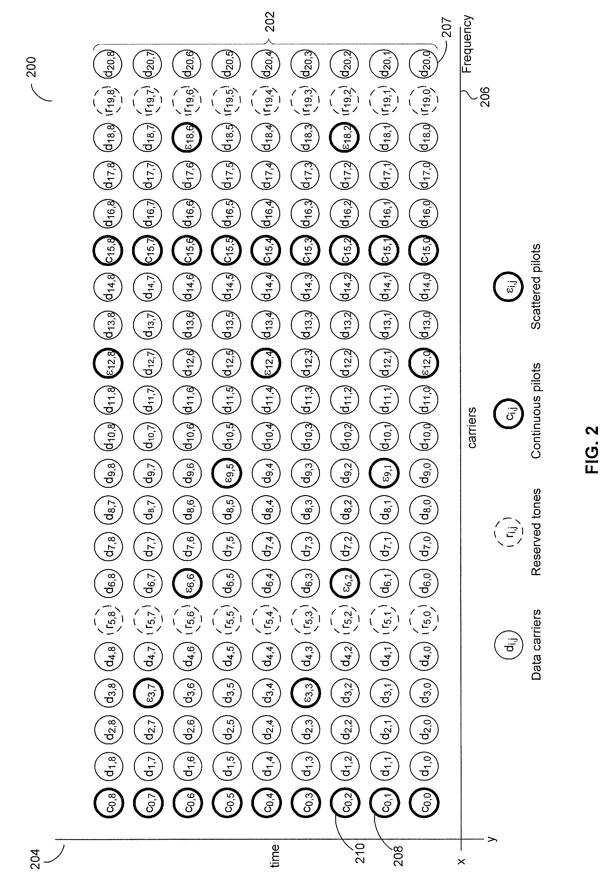
[0026]OFDM systems contain both continuous and scattered pilots. For common phase error correction, continuous pilots are used as discussed above. In the present invention, however, instead of using continuous pilots for phase error correction, a modulated scattered pilot sequence is used to enable the performance of both coarse and fine synchronization in the time domain. That is, the continuous pilots can be used to assist and perform fine synchroniza...


PUM


Abstract

Provided is a method for synchronizing a multiple carrier receiver to receive a transmitted signal. The method includes determining a location of one or more scattered pilot carriers in a received symbol sequence and modulating the scattered pilot carriers in accordance with a single pseudorandom binary sequence. The method also includes performing phase error correction via the modulated scattered pilot carriers.

Description

CROSS-REFERENCE TO RELATED APPLICATIONS / INCORPORATION BY REFERENCE[0001]This patent application makes reference to, claims priority to and claims benefit from U.S. Provisional Patent Application Ser. No. 61 / 116,532 filed on Nov. 20, 2008.[0002]The above stated application is hereby incorporated herein by reference in its entirety.FIELD OF THE INVENTION[0003]The present invention generally relates to digital video broadcasting (DVB). More specifically, the present invention relates to synchronizing transmitted data in a multi-carrier modulation based receiver used in a DVB system.BACKGROUND OF THE INVENTION[0004]DVB is the European consortium standard for the broadcast transmission of digital terrestrial television. DVB systems transmit a compressed digital audio / video stream, using multi-carrier modulation, such as orthogonal frequency division multiplexing (OFDM). Another popular method of transmitting signals is digital video broadcasting-terrestrial (DVB-T). When broadcasters emp...

Claims


Application Information

Patent Timeline
Patent Type & Authority Patents(United States)
IPC IPC(8): H04L27/00
CPCH04L5/0048H04L27/2613H04L27/2657H04L27/2671H04J13/0051H04L5/0007H04L27/2662H04L7/00H04L27/26
Inventor RAJAGOPAL, RAVIKIRAN
Owner AVAGO TECH INT SALES PTE LTD
Why Eureka
Try Eureka