Drive controller and drive control method for electric motor

a technology of drive controller and electric motor, which is applied in the direction of motor/generator/converter stopper, dynamo-electric gear control, dynamo-electric converter control, etc., and can solve problems such as possible instability of control operation

Active Publication Date: 2012-09-18
TOYOTA JIDOSHA KK +1
View PDF14 Cites 21 Cited by
  • Summary
  • Abstract
  • Description
  • Claims
  • Application Information

AI Technical Summary

Benefits of technology

[0005]The present invention was made to solve such a problem and an object of the present invention is, in a drive controller and a drive control method for an AC electric motor having a configuration allowing switching between control modes, to appropriately execute switching of control modes without making unstable the operation of AC electric motor.
[0008]According to the drive controller or drive control method for the AC electric motor described above, when the control mode is switched from the first control mode (rectangular wave voltage control mode) to the second control mode (PWM control mode), the voltage applied to the AC electric motor can be maintained from the mode switching determination to the actual execution of mode switching. As a result, state change of AC electric motor in the time lag (corresponding to one operation period of the mode switching determining unit) from the mode switching determination to the execution of mode switching, which possibly results in unstable control of AC electric motor at the time of mode switching, can be prevented.
[0011]According to the drive controller or drive control method for the AC electric motor described above, when the first control mode (rectangular wave voltage control mode) is selected, AC electric motor is controlled in the first control mode while feedback control calculation for the second control mode (PWM control mode) is executed in parallel. Therefore, when conditions for switching from the first control mode to the second control mode are satisfied, the AC electric motor control in accordance with the second control mode can immediately be started, using the result of control calculation that has been performed in parallel. Therefore, control mode can be switched quickly without making electric motor control unstable.
[0013]This prevents increase in calculation load imposed as the control calculation for the second control mode is executed while the first control mode is selected. As a result, control calculation in accordance with the second control mode can be executed in parallel without affecting AC electric motor control in accordance with the first control mode.
[0015]This prevents unstable AC electric motor control at the time of switching to the second control mode, which would otherwise be caused as the control calculation for the second control mode while the first control mode is selected is divided at a plurality of timings and executed successively to alleviate calculation load.
[0018]Therefore, according to the present invention, in the drive controller for an AC electric motor having a configuration allowing switching between control modes, control mode can appropriately be switched without making unstable the operation of AC electric motor at the transition between control modes, particularly at the transition from the rectangular wave voltage control mode to the PWM control mode.

Problems solved by technology

If such a situation occurs, control operation could possibly be unstable particularly at the transition from the rectangular wave voltage control mode to the PWM control mode.

Method used


Image

  • Drive controller and drive control method for electric motor
  • Drive controller and drive control method for electric motor
  • Drive controller and drive control method for electric motor

Examples


embodiment 1

[0083](Control Mode Switching Process of Embodiment 1)

[0084]Next, the control mode switching process in accordance with Embodiment 1 of the present invention will be described.

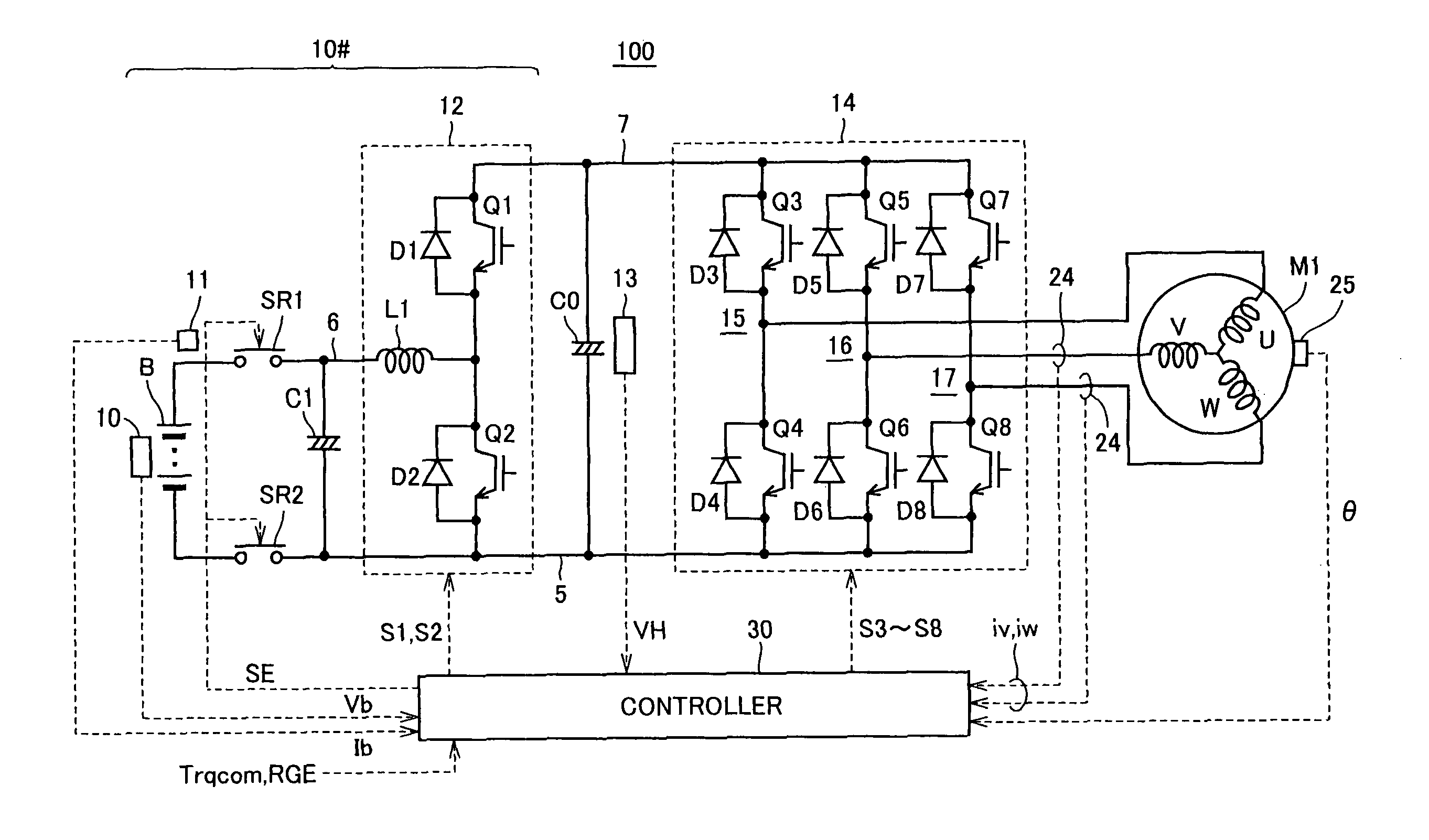
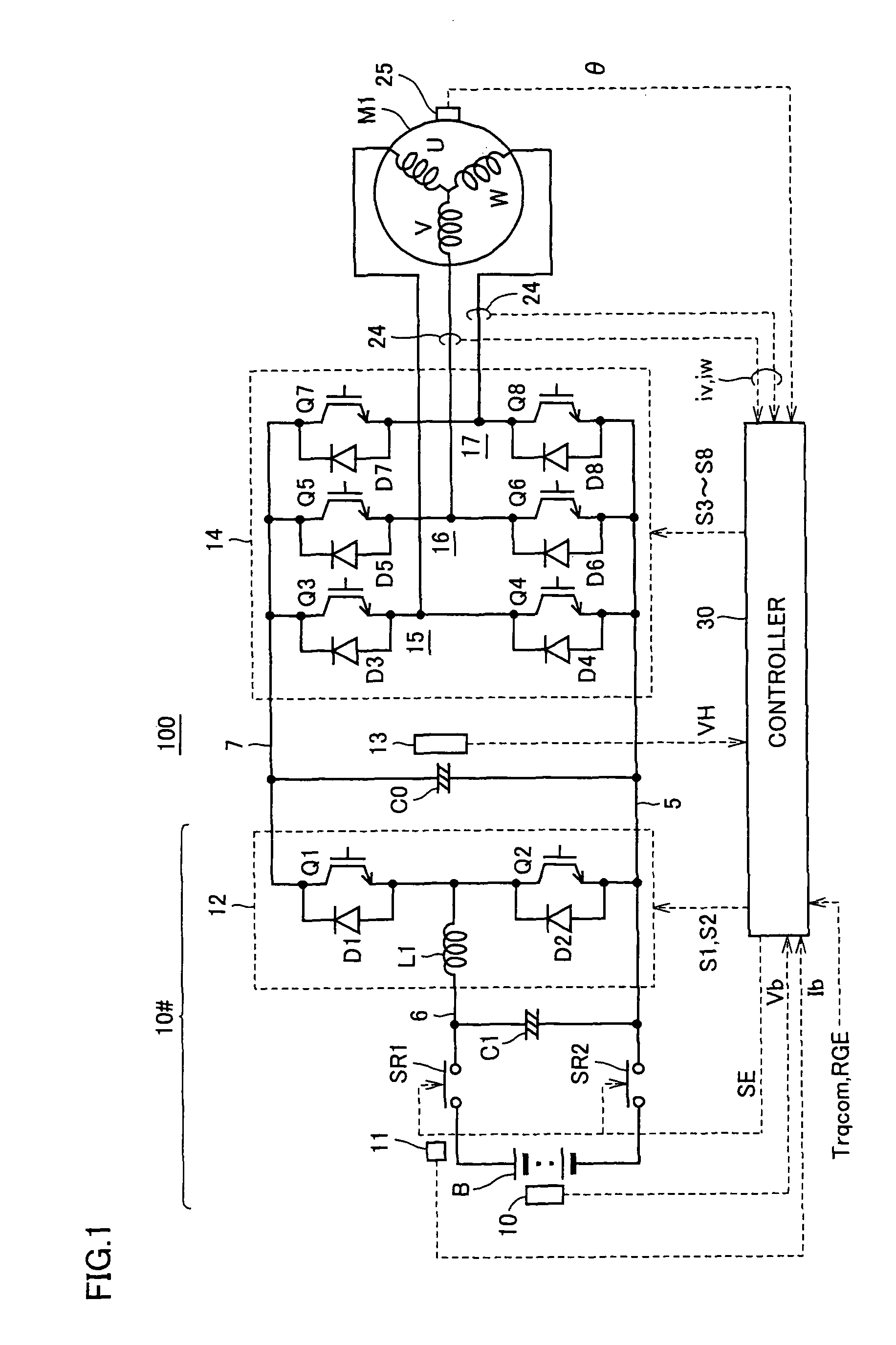
[0085]As shown in FIG. 4, mode switching determining unit 400 executes the mode switching determination based on the motor current MCRT detected by the current sensor, the input voltage VH of inverter 14 detected by voltage sensor 13, and the voltage amplitude |V| and voltage phase φv of the voltage command generated by current control unit 220. By way of example, when controller 30 executes the control process in accordance with the flowchart of FIG. 6, the mode switching determination by mode switching determining unit 400 is realized.

[0086]Referring to FIG. 6, first, controller 30 determines whether the present control mode is the PWM control mode or not, at step S100. If the present control mode is the PWM control mode (determination of YES at S100), controller 30 calculates, at step S110, a modulation fac...

embodiment 2

[0105](Control Mode Switching Process of Embodiment 2)

[0106]As described in Embodiment 1, in order to realize smooth transition of control mode, it is necessary that the result of control calculation for executing PWM control is already available by the time of control mode switching. In Embodiment 2, a control structure that allows immediate switching of control mode, without necessitating wait for one period of the main loop from the mode switching determination (from rectangular wave voltage control mode to the PWM control mode) by mode switching determining unit 400 will be described.

[0107]FIG. 10 is a flowchart representing the control calculation process in the rectangular wave control mode, by the drive controller for an AC electric motor in accordance with Embodiment 2.

[0108]Referring to FIG. 10, controller 30 determines, at step S200, whether the control mode is the rectangular wave voltage control-mode or not. If the rectangular wave voltage control mode is not selected (d...


PUM


Abstract

Control mode switching determination is made as a part of a main loop (control period for overall control of an AC electric motor. When switching from the rectangular wave voltage control mode to PWM control mode is determined, the change in voltage phase of the rectangular wave voltage is inhibited from the timing of control mode switching determination until the next execution of the main loop until the timing at which the control mode is actually switched, to maintain voltage phase of the rectangular wave voltage at the time of control mode switching determination. Consequently, in a drive controller for an AC electric motor allowing switching between control modes, control mode can appropriately be switched without destabilizing the operation of the AC electric motor.

Description

TECHNICAL FIELD[0001]The present invention relates to a drive controller and a drive control method for an electric motor and, more specifically, to control of an AC electric motor having a plurality of switchable control modes.BACKGROUND ART[0002]A configuration for controlling driving of an AC electric motor by converting DC voltage to AC voltage using a converter has been generally used. In such a configuration, generally, motor current is controlled in accordance with pulse width modulation (PWM) based on vector control. Further, configurations for controlling AC electric motor by switching between a rectangular wave voltage phase control mode in which drive control is attained by applying a rectangular wave voltage to the AC electric motor and a PWM current control mode based on PWM control have been known from Japanese Patent Laying-Open Nos. 2005-218299, 2001-78495, 2002-223590 and 2005-45880.[0003]In the drive controllers for AC electric motors disclosed in these references,...

Claims


Application Information

Patent Timeline
Patent Type & Authority Patents(United States)
IPC IPC(8): H02P1/04H02M1/00H02P23/07H02P25/04H02P27/08
CPCH02M7/00H02P21/0089H02P27/08H02M2001/0012H02P2201/09H02M1/0012
Inventor ITOH, TAKESHI
Owner TOYOTA JIDOSHA KK
Why Eureka
Try Eureka