Movable contact assembly of electromagnetic switch

a technology of electromagnetic switch and contact assembly, which is applied in the direction of contact mechanism, relay, snap-action arrangement, etc., can solve the problems of inconvenient assembly process, complicated assembly process, and inconvenient assembly process, so as to facilitate and facilitate assembly and facilitate the process of carrying out, the effect of easy and convenient assembly

Active Publication Date: 2012-09-18
LSIS CO LTD
View PDF10 Cites 28 Cited by
  • Summary
  • Abstract
  • Description
  • Claims
  • Application Information

AI Technical Summary

Benefits of technology

[0012]A task of the present invention is to solve the foregoing problem, and there is provided an electromagnetic switch capable of enhancing the assembly performance to simplify the process.
[0014]According to the foregoing aspect of the present invention, the movable contact may be fixed in a snap-fit manner by a hook other than a corking manner in the related art, thereby further facilitating the assembly process.
[0017]Furthermore, a head having a pair of rib portions protruded in parallel to each other may be provided at the shaft, and both lateral surfaces of the movable contact may be supported between the pair of the rib portions to prevent rotation using the shaft as a rotational axis.
[0020]According to the present invention, a movable contact assembly may be assembled in a snap-fit manner. Accordingly, a movable contact, or even a push spring if necessary, may be easily and conveniently assembled with respect to a shaft without fixing the movable contact by a jig as well as without using a punch. As a result, the assembly can be easily and conveniently carried out, and the assembly process may be also simplified compared to the existing corking method.

Problems solved by technology

Accordingly, it may have a drawback that the overall assembly process is complicated and inconvenient.
As a result, it may have a drawback that the assembly process is further complicated.

Method used


Image

  • Movable contact assembly of electromagnetic switch
  • Movable contact assembly of electromagnetic switch
  • Movable contact assembly of electromagnetic switch

Examples


Embodiment Construction

[0027]Hereinafter, an electromagnetic switch according to a preferred embodiment of the present invention will be described in detail with reference to the accompanying drawings.

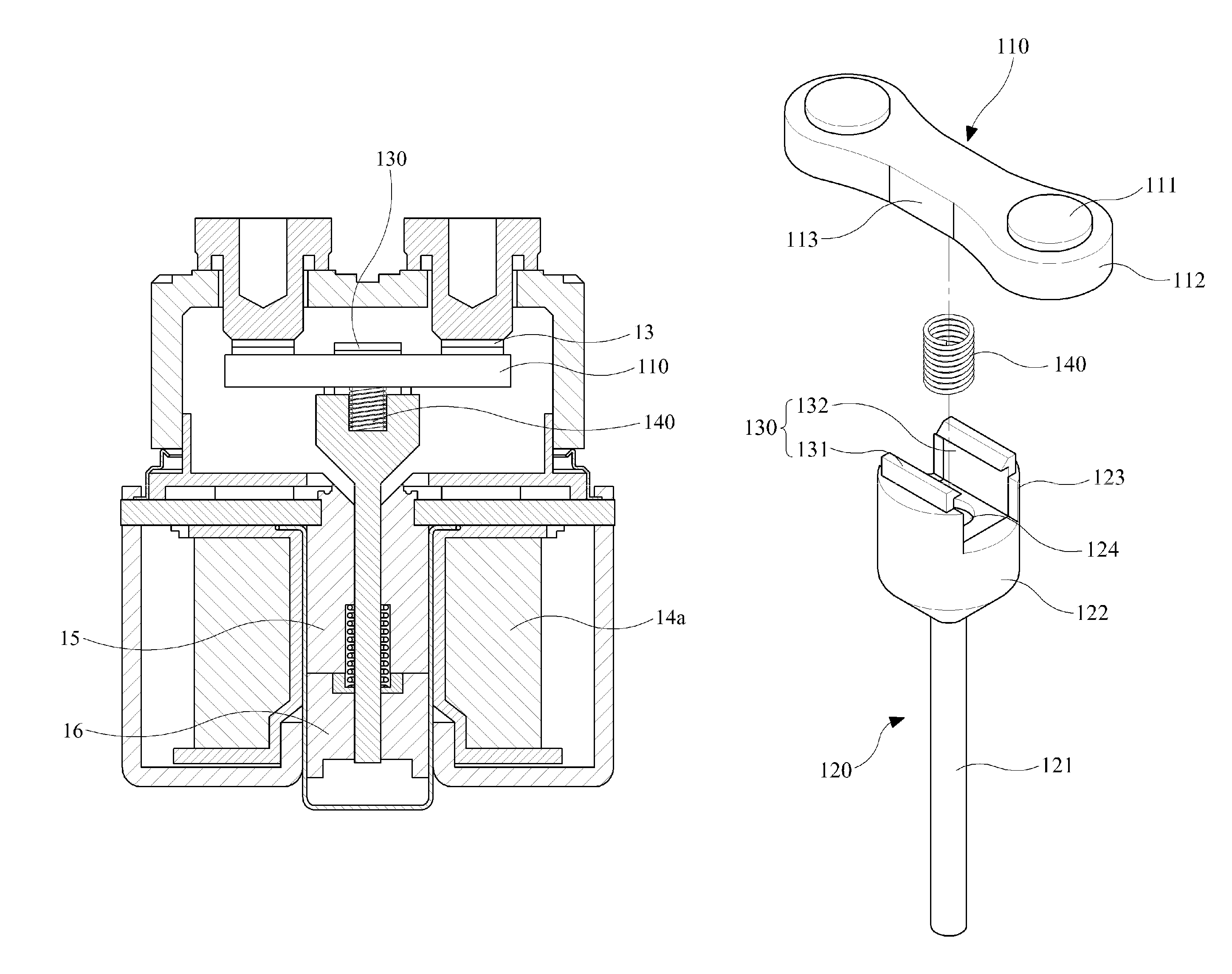
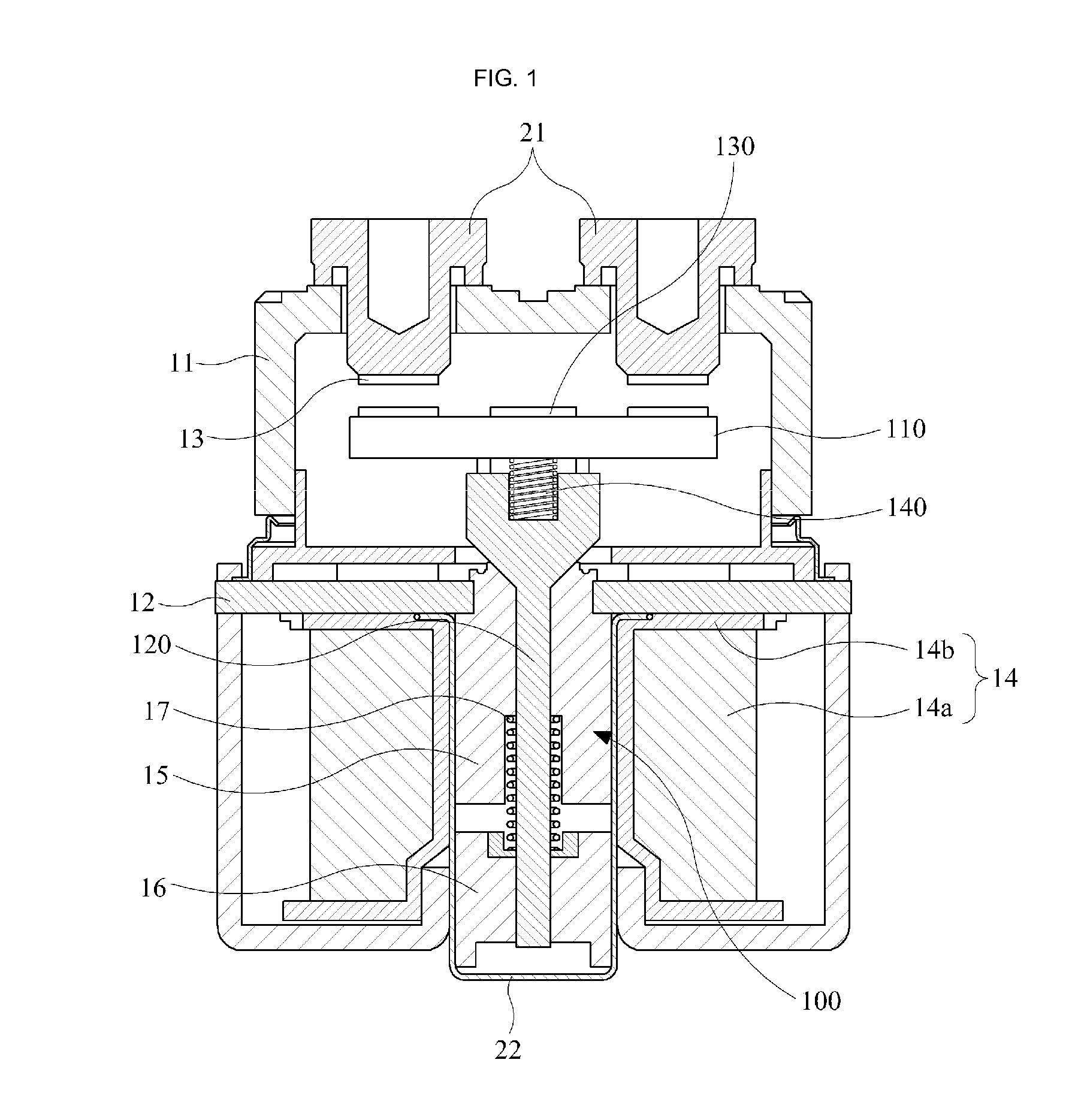
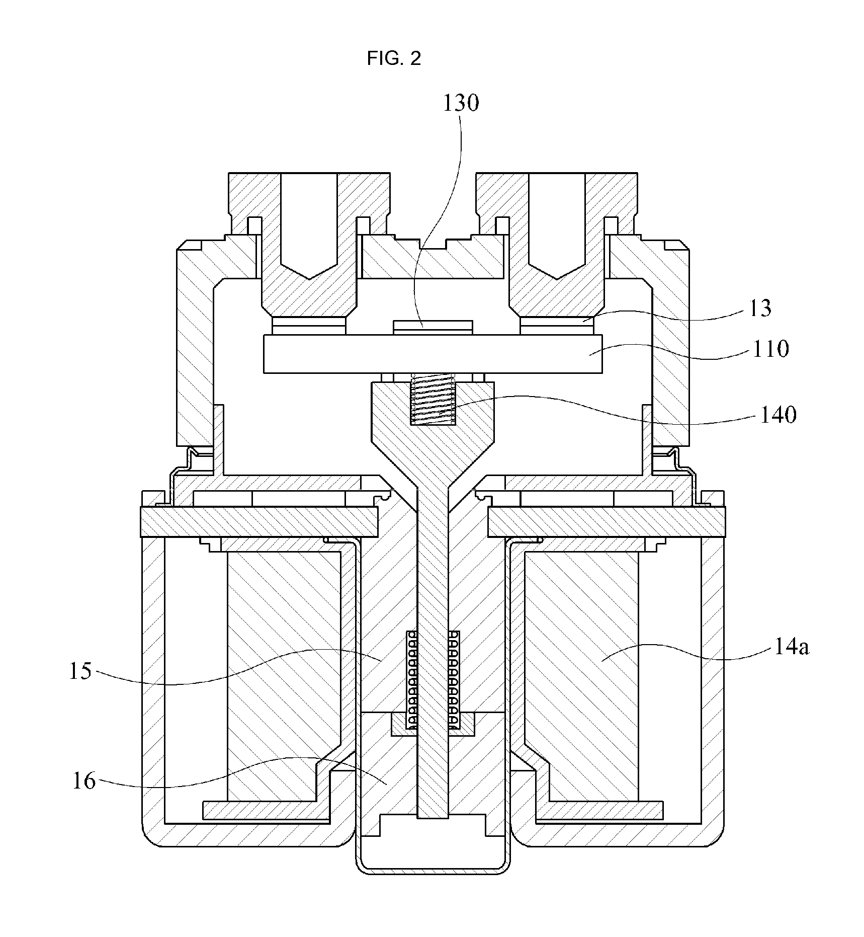
[0028]FIG. 1 is a cross-sectional view illustrating an example of an electromagnetic switch to which a movable contact assembly according to an embodiment of the present invention is applied, and FIG. 2 is a cross-sectional view illustrating a configuration in which a movable contact is moved to be brought into contact with a stationary contact in FIG. 1, and FIG. 3 is an exploded perspective view illustrating a movable contact assembly in FIG. 1, and FIG. 4 is a perspective view illustrating a configuration in which the movable contact assembly of FIG. 3 is assembled.

[0029]Referring to FIGS. 1 through 4, an electromagnetic switch may include a cover portion 11, a plate 12, a stationary contact 13, a coil assembly 14, a stationary core 15, a movable core 16, and a return spring 17.

[0030]The cover portion 11 ...


PUM


Abstract

An electromagnetic switch includes: a stationary contact; a movable contact movably provided with respect to the stationary contact; a coil configured to move the movable contact to a side of the stationary contact by means of current conduction; and a shaft provided inside the coil such that the movable contact is provided at an end portion thereof, wherein a snap-fit portion having a pair of hooks disposed to face each other is provided at an end portion of the shaft, and the movable contact is fixed between the end portion of the shaft and the hook.

Description

CROSS-REFERENCE TO RELATED APPLICATIONS[0001]This application claims the benefit of Korean Patent Application No. 10-2010-0100772, filed on Oct. 15, 2010, which is hereby incorporated by reference for all purposes as if fully set forth herein.BACKGROUND OF THE INVENTION[0002]1. Field of the Invention[0003]The present invention relates to a movable contact assembly employed in an electromagnetic switch.[0004]2. Description of the Related Art[0005]In general, an electromagnetic switch may be provided between a storage battery and a power converting device in an electric vehicle such as a hybrid vehicle, a fuel cell vehicle, a golf cart, and an electric forklift to perform the function of supplying and cutting off power provided from the storage battery to the power converting device.[0006]The electromagnetic switch may include a stationary contact, a movable contact brought into contact with or separated from the stationary contact, and an electronic actuator for driving the movable c...

Claims


Application Information

Patent Timeline
Patent Type & Authority Patents(United States)
IPC IPC(8): H01H67/02H01H3/00
CPCH01H1/2008H01H50/546H01H1/32
Inventor CHOI, YEON SOON
Owner LSIS CO LTD
Why Eureka
Try Eureka