Electronic device module with movable shield for anti-electromagnetic interference

a technology of electromagnetic interference and electronic devices, applied in the direction of lighting and heating apparatus, electric apparatus casings/cabinets/drawers, instruments, etc., can solve the problems of reducing heat dissipation efficiency, prone to being lost, and extra shields

Inactive Publication Date: 2012-09-18
HONG FU JIN PRECISION IND (SHENZHEN) CO LTD +1
View PDF7 Cites 9 Cited by
  • Summary
  • Abstract
  • Description
  • Claims
  • Application Information

AI Technical Summary

Benefits of technology

[0004]Oftentimes, electronic devices such as data storage devices need to be detached from enclosures of electronic systems, thereby leaving an opening in the enclosures. The opening may permit electromagnetic interference (EMI), and misdirect the airflow in the enclosure, thereby reducing heat dissipation efficiency. Typically, an extra shield is used to cover the opening. However, the extra shield may increase cost and is prone to being lost, which is inconvenient.

Problems solved by technology

The opening may permit electromagnetic interference (EMI), and misdirect the airflow in the enclosure, thereby reducing heat dissipation efficiency.
However, the extra shield may increase cost and is prone to being lost, which is inconvenient.

Method used


Image

  • Electronic device module with movable shield for anti-electromagnetic interference
  • Electronic device module with movable shield for anti-electromagnetic interference
  • Electronic device module with movable shield for anti-electromagnetic interference

Examples


Embodiment Construction

[0010]The disclosure, including the accompanying drawings, is illustrated by way of examples and not by way of limitation. It should be noted that references to “an” or “one” embodiment in this disclosure are not necessarily to the same embodiment, and such references mean at least one.

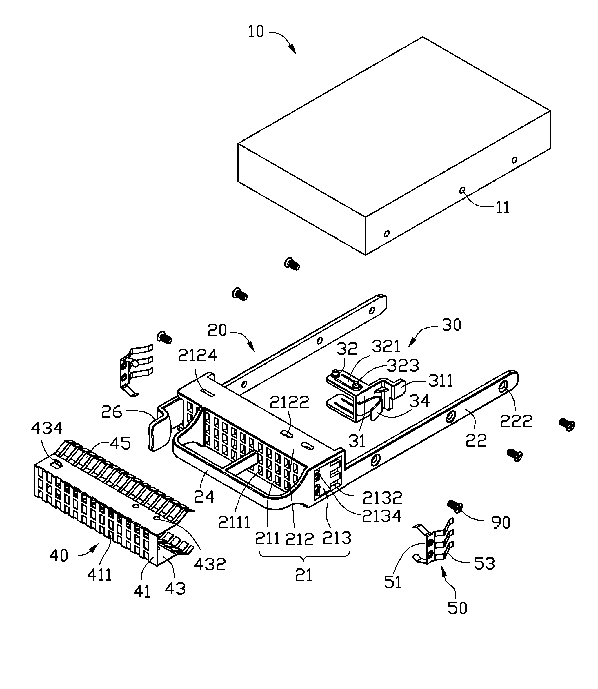
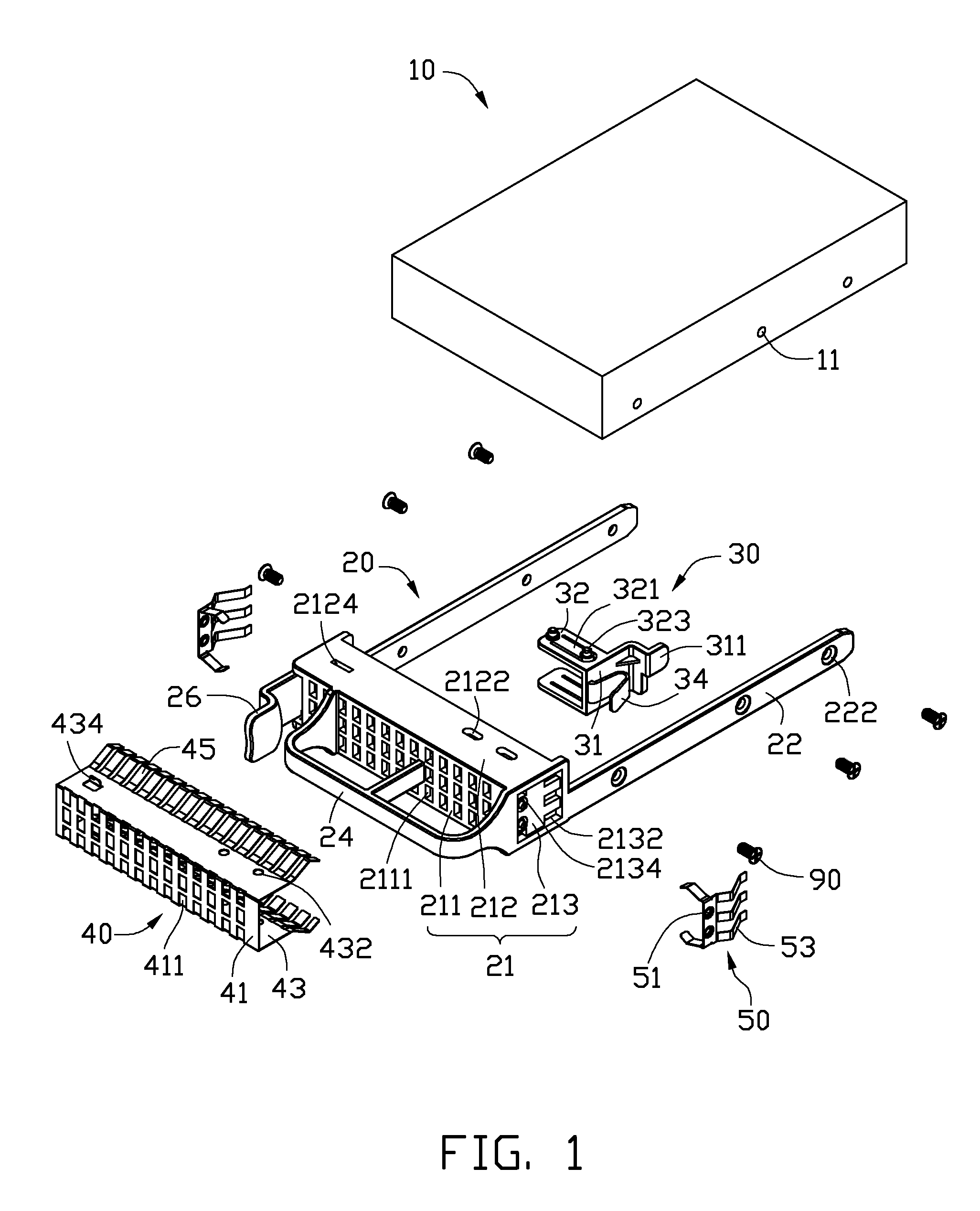
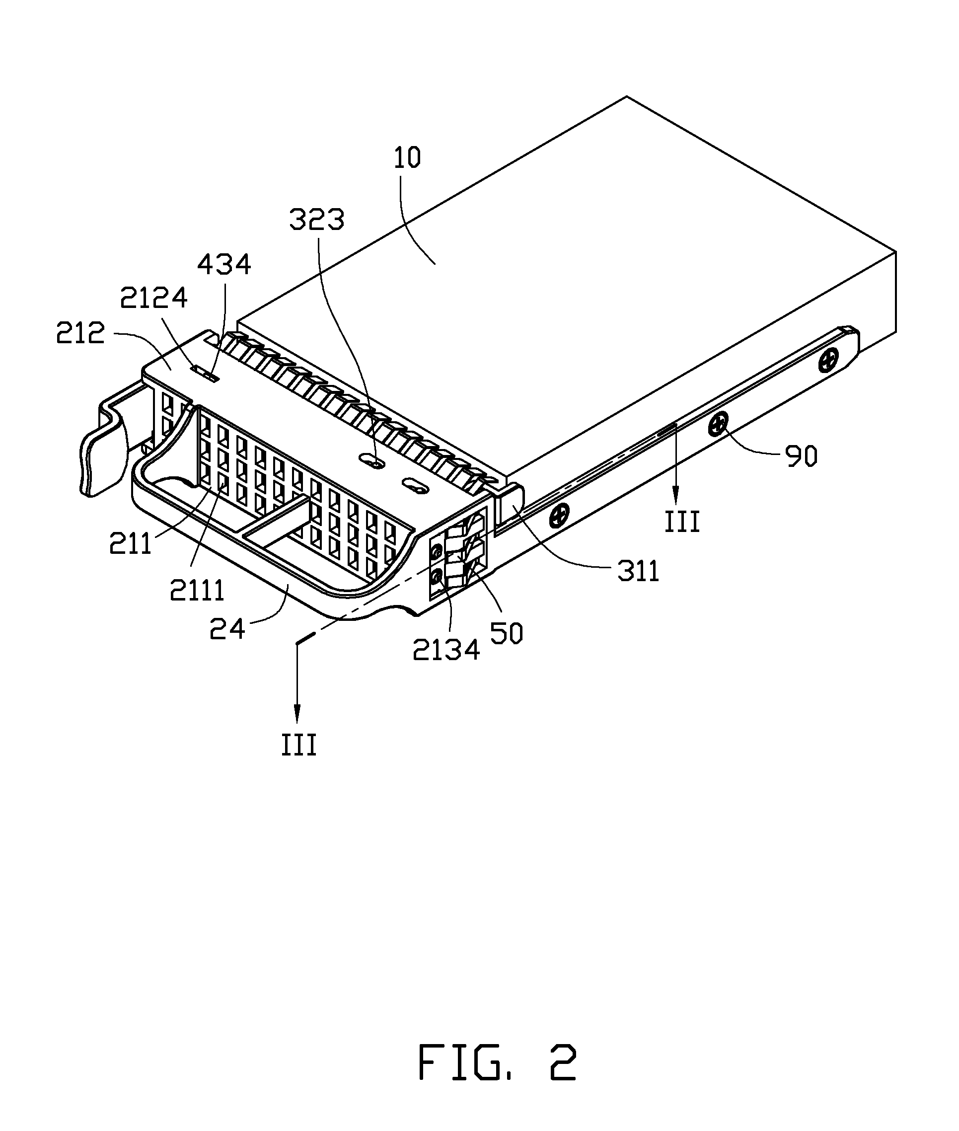
[0011]Referring to FIG. 1, one embodiment of an electronic device module includes a mounting apparatus, and an electronic device mounted in the mounting apparatus. In this embodiment, the electronic device is a data storage device 10. The mounting apparatus includes a rack 20 for holding the data storage device 10, a shield adjusting assembly movably attached to the rack 20, two anti-EMI plates 50, and a plurality of fasteners. In this embodiment, the shield adjusting assembly includes a movable member 30 and a shield 40, and the fasteners are screws 90.

[0012]The data storage device 10 includes a plurality of mounting holes 11 in two opposite sides thereof.

[0013]The rack 20 includes a main body 21 and...


PUM


Abstract

An electronic device module includes an electronic device, a rack accommodating the electronic device, and a shield adjusting assembly. The rack defines a number of ventilation holes, and the shield adjusting assembly defines a number of through holes. The electronic device is placed in the rack to drive the shield adjusting assembly to a first position in which the through holes align with the ventilation holes. When the electronic device is detached from the rack, the shield adjusting assembly is restored by a resilient element to a second position in which the through holes offset the ventilation holes such that the ventilation holes are shielded.

Description

BACKGROUND[0001]1. Technical Field[0002]The present disclosure relates to an electronic device module and, particularly, to an electronic device module having anti-electromagnetic interference (anti-EMI) efficiency.[0003]2. Description of Related Art[0004]Oftentimes, electronic devices such as data storage devices need to be detached from enclosures of electronic systems, thereby leaving an opening in the enclosures. The opening may permit electromagnetic interference (EMI), and misdirect the airflow in the enclosure, thereby reducing heat dissipation efficiency. Typically, an extra shield is used to cover the opening. However, the extra shield may increase cost and is prone to being lost, which is inconvenient.BRIEF DESCRIPTION OF THE DRAWINGS[0005]Many aspects of the present embodiments can be better understood with reference to the following drawings. The components in the drawings are not necessarily drawn to scale, the emphasis instead being placed upon clearly illustrating the...

Claims


Application Information

Patent Timeline
Patent Type & Authority Patents(United States)
IPC IPC(8): H05K7/20H05K5/00F28F7/00
CPCH05K9/0041
Inventor PENG, WEN-TANGGONG, XIN-HUXIA, GAO-LIANG
Owner HONG FU JIN PRECISION IND (SHENZHEN) CO LTD
Why Eureka
Try Eureka