Adiabatic coupler for coiled optical fiber devices

a technology of optical fiber and coupler, which is applied in the direction of optics, optical light guides, instruments, etc., can solve the problems of large mismatch between the coil and the conventional input/output waveguide or fiber, and the difficulty of coupling an input signal, etc., and achieve the effect of low loss transmission

Active Publication Date: 2012-09-18
OFS FITEL LLC
View PDF6 Cites 10 Cited by
  • Summary
  • Abstract
  • Description
  • Claims
  • Application Information

AI Technical Summary

Benefits of technology

[0007]In accordance with the present invention, a section of optical fiber is utilized as an adiabatic optical coupler between a conventional input optical signal (propagating along an optical fiber or waveguide) and a coiled optical fiber device. The section of optical fiber may itself be coiled (or, at least, curved) to assist in transforming the conventional fundamental mode propagating along the longitudinal axis of the input fiber / waveguide to an off-axis fundamental mode that is shifted into a peripheral region of an associated coiled optical fiber device.
[0008]For embodiments where the adiabatic optical coupler is itself formed into a coil, the pitch of the coil can also be controlled to assist in the adiabatic transformation process.
[0009]In a preferred embodiment, the adiabatic optical fiber coupler remains physically separated from the turns of the associated coiled optical fiber device (as well as a central core rod, if included in the coiled optical fiber device) in order to ensure low loss transmission of the fundamental mode, without coupling any signal into the central core rod or individual turns of the coil.

Problems solved by technology

While the confinement of the propagating mode to a shifted, peripheral region of the optical fiber improves the performance of the device, difficulties remain in coupling an input signal to the optical fiber coil, or extracting an optical signal therefrom.
One problem may be associated with the large mismatch between the coil and a conventional input / output waveguide or fiber in terms of, for example, physical dimension, modefield diameter and propagation constant.

Method used


Image

  • Adiabatic coupler for coiled optical fiber devices
  • Adiabatic coupler for coiled optical fiber devices
  • Adiabatic coupler for coiled optical fiber devices

Examples


Embodiment Construction

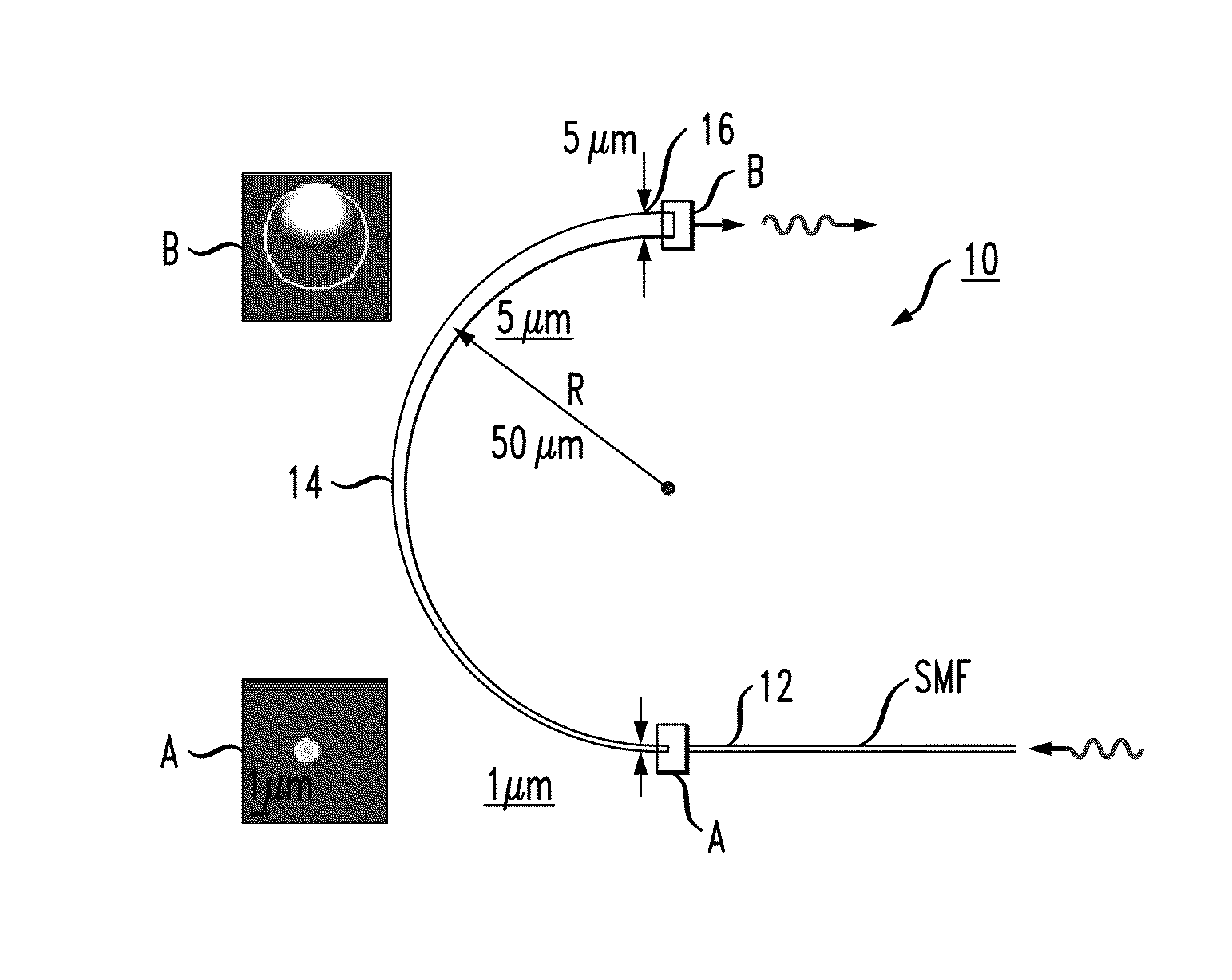
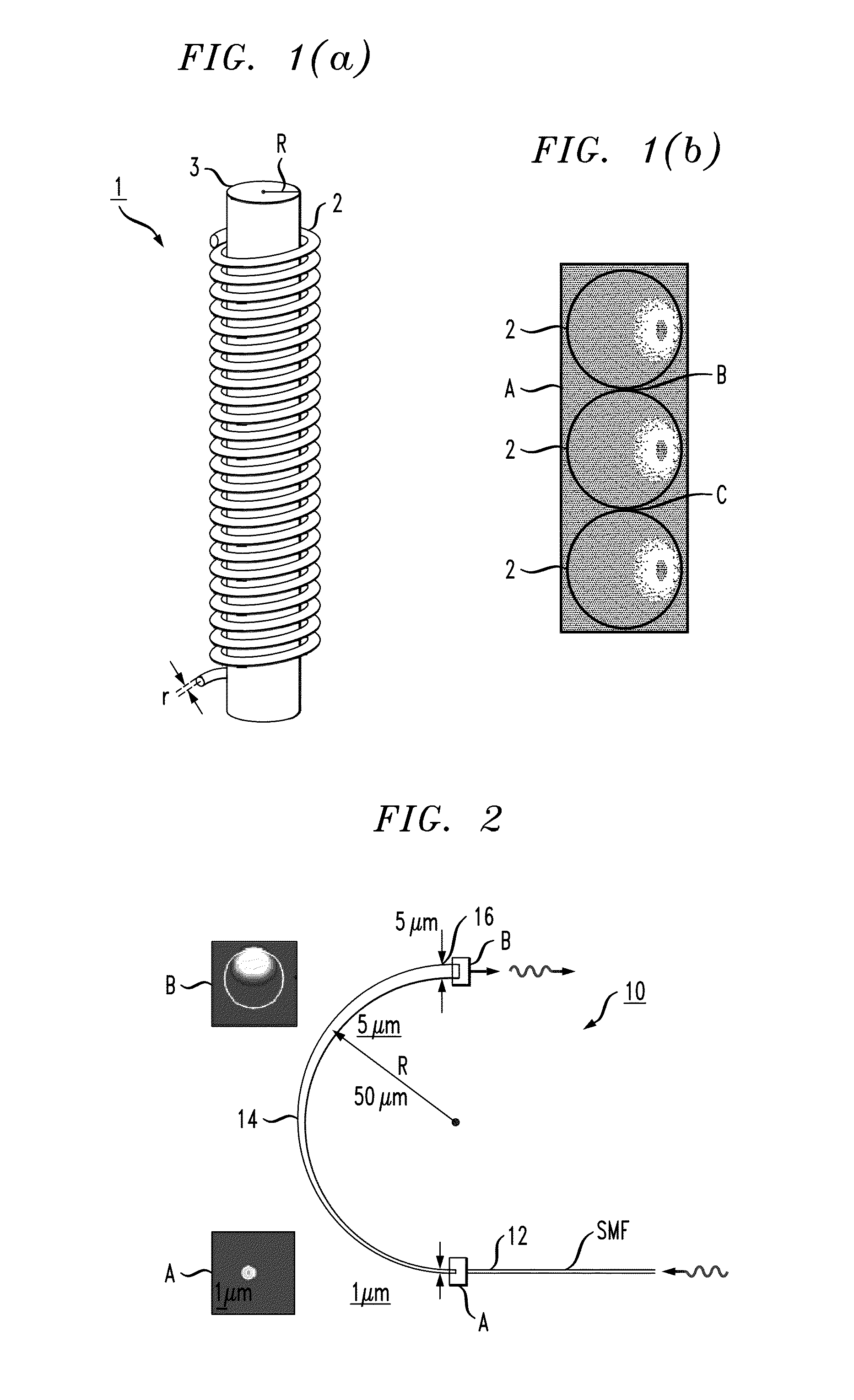
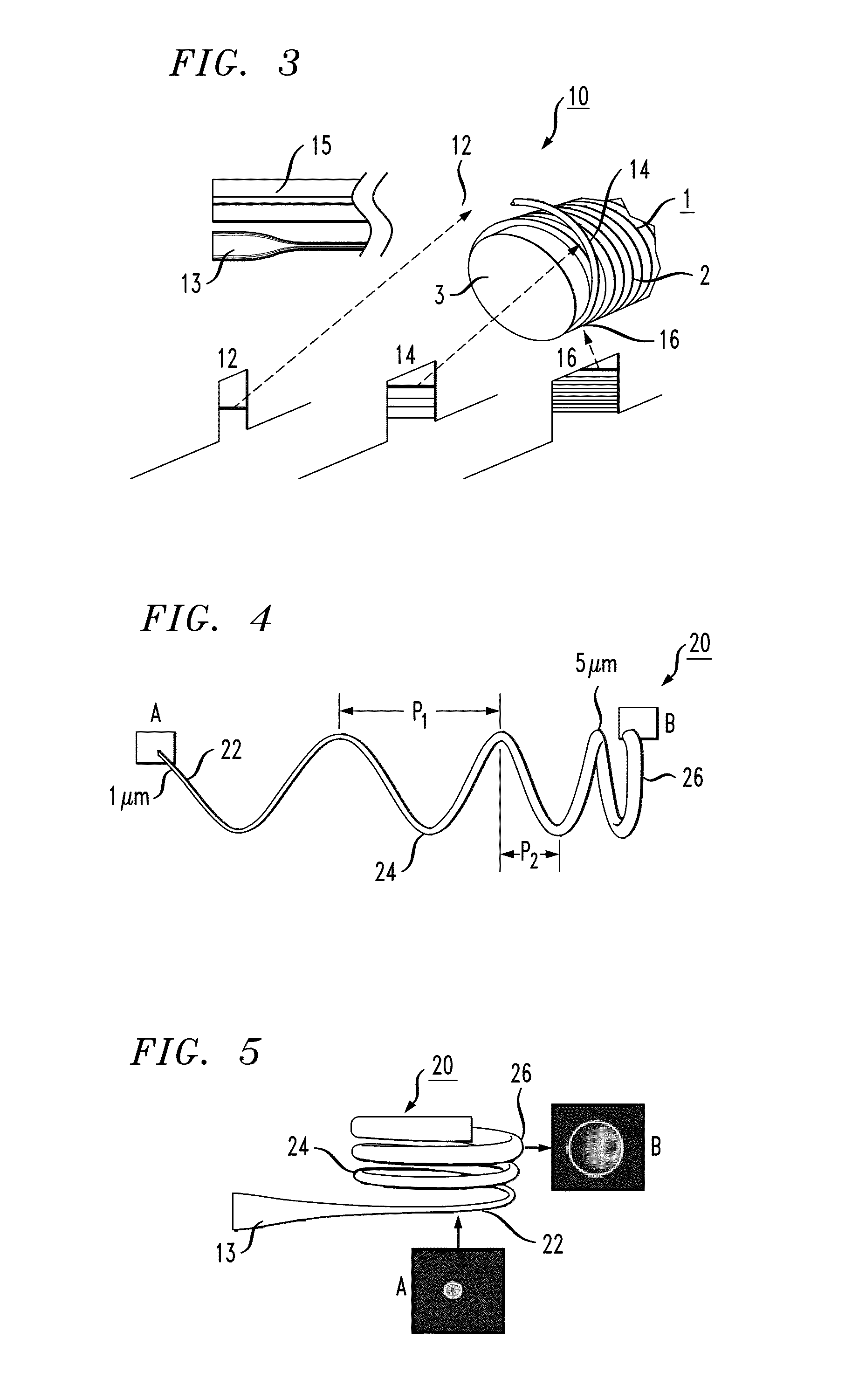
[0027]FIG. 1(a) illustrates an exemplary optical fiber coil 1 as disclosed in my co-pending application. The propagating fundamental mode is shown in FIG. 1(b) as being confined to an extreme outer peripheral region of each turn 2 of optical fiber along the coil. By confining the propagating mode to this region, the coupling between adjacent turns—as well as between the turns and a central core rod 3—is significantly reduced, allowing for propagation with little or no scattering and / or bending losses.

[0028]While this configuration is considered a significant improvement over other types of optical delay devices, the ability to couple a propagating signal into or out of the desired extreme peripheral region of the fiber coil remains problematic. A suitable coupling arrangement needs to also address the physical size differences between standard input / output waveguides or fibers and the “micro” dimensions of an optical microfiber when using a microfiber to form coil 1.

[0029]The presen...


PUM


Abstract

An optical fiber coupler is formed of a section of optical fiber that is positioned between a conventional input fiber (for example, a single mode fiber) or waveguide and a coiled optical fiber device. The adiabatic coupler is coiled (or, at least, curved) to assist in transforming a conventional fundamental mode optical signal propagating along the longitudinal axis of the input fiber to an optical signal that is shifted into a peripheral region of the coiled optical fiber. Moreover, the pitch of an inventive coiled optical fiber coupler can be controlled to assist in the adiabatic transformation process.

Description

CROSS-REFERENCE TO RELATED APPLICATIONS[0001]This application claims the benefit of U.S. Provisional Application No. 61 / 153,777 filed Feb. 19, 2009 and U.S. Provisional Application No. 61 / 156,565 filed Mar. 2, 2009, both of which are hereby incorporated by reference.TECHNICAL FIELD[0002]The present invention relates to a coupler for use with coiled optical fiber devices and, more particularly, to a device for adiabatic transformation of a propagating optical signal into a preferred modefield distribution for an optical signal propagating in an optical fiber coil.BACKGROUND OF THE INVENTION[0003]Optical pulse buffers are important for optical communications and ultra-fast computing. An exemplary preferred type of buffer, comprising an optical fiber coil, is disclosed in my co-pending U.S. patent application Ser. No. 12 / 587,767, filed Oct. 13, 2008. In this preferred buffer, the radii of the optical fiber and coil are selected to confine the propagating fundamental mode in a region th...

Claims


Application Information

Patent Timeline
Patent Type & Authority Patents(United States)
IPC IPC(8): G02B6/26G02B6/42
CPCG02B6/305
Inventor SUMETSKY, MIKHAIL
Owner OFS FITEL LLC
Why Eureka
Try Eureka