
Viewing device for aircraft comprising means of displaying trajectories of intruders presenting a risk of collision in all the space surrounding the aircraft

a viewing device and aircraft technology, applied in the direction of instruments, navigation instruments, using reradiation, etc., can solve the problems of large number of fatal accidents, new systems are inadequate for carrying out missions at low altitude,

Active Publication Date: 2012-09-18
THALES SA
View PDF6 Cites 13 Cited by
  • Summary
  • Abstract
  • Description
  • Claims
  • Application Information

AI Technical Summary

Benefits of technology

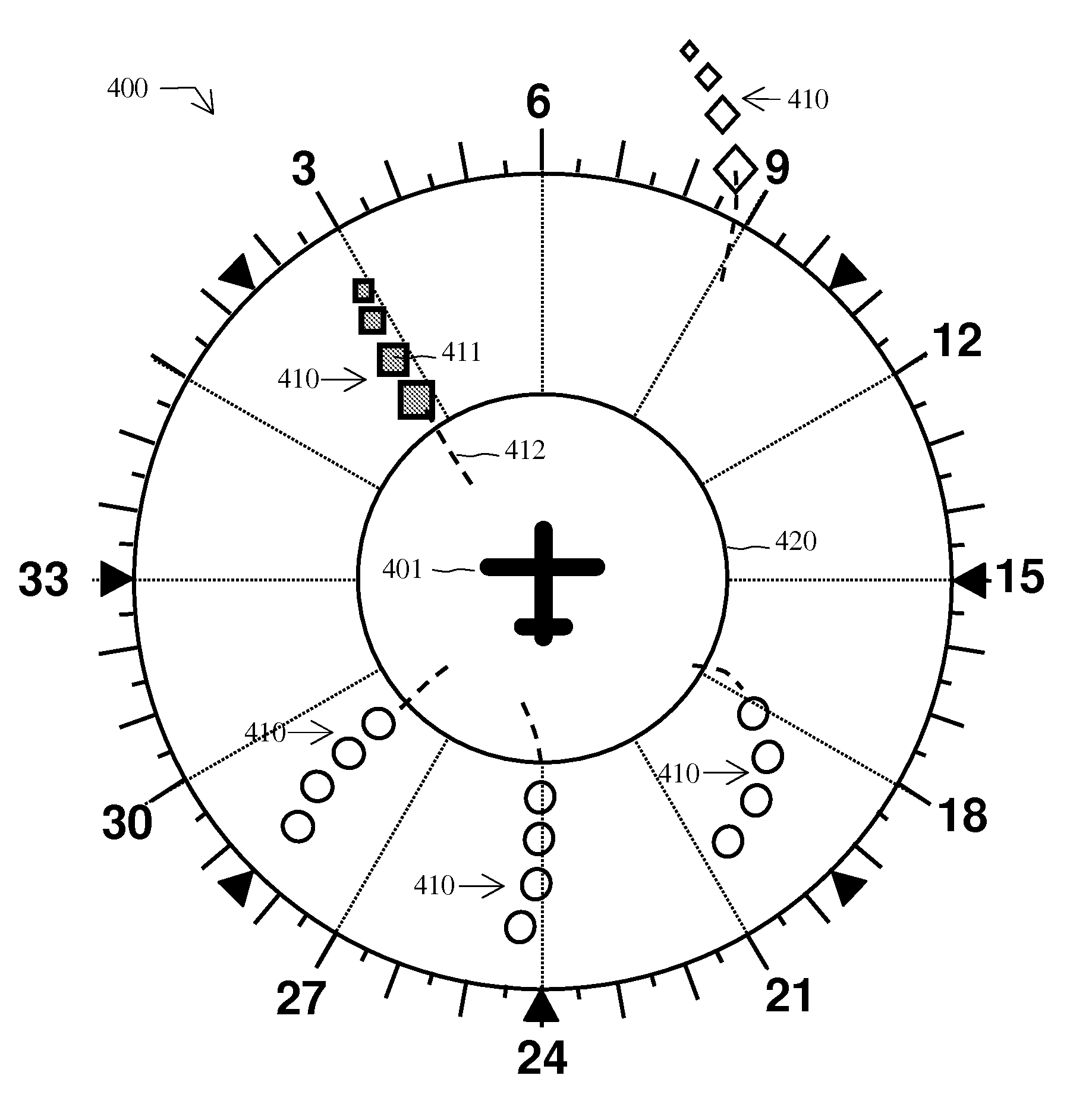
The invention is a system that helps pilots see the space around their aircraft more clearly. It uses sensors and a computer to create a virtual image of the space, which includes symbols of the pilot's aircraft and the positions of other aircraft that may be a threat. The system also predicts the future trajectory of the other aircraft. The virtual image can be displayed on a screen in front of the pilot, making it easier to see the space around the aircraft. The system can also include a representation of a protection area around the pilot's aircraft that changes appearance when the other aircraft is inside or will penetrate it. Overall, the system helps pilots better understand the space around their aircraft and reduces the risk of collisions.

Problems solved by technology

This problem is particularly crucial in a certain number of applications where the aircraft are required to fly at low altitude with possibly reduced visibility conditions.
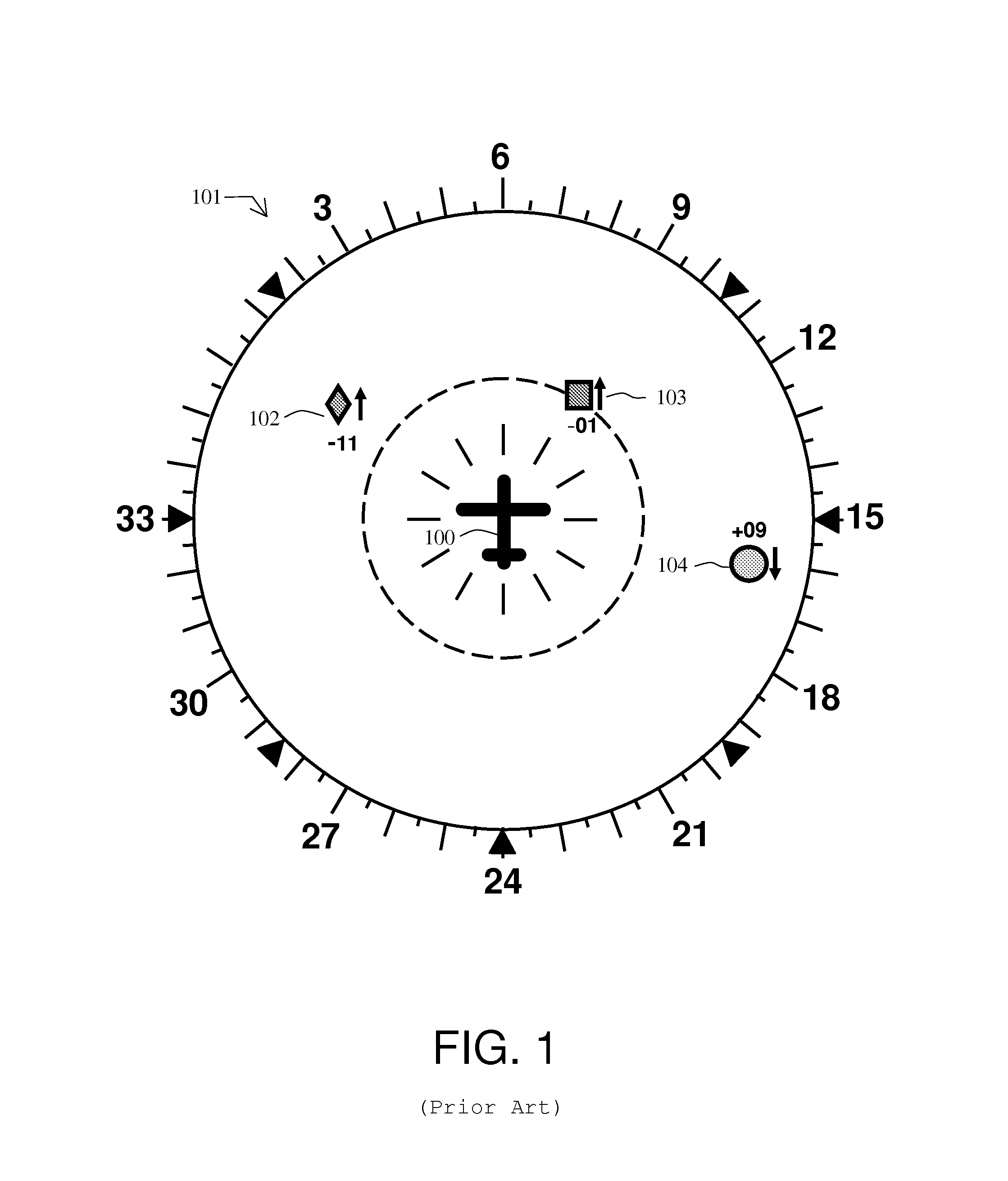
As can be seen, the interpretation of the information by the pilot is far from immediate, which can prove particularly dangerous in cases of imminent risk of collision.
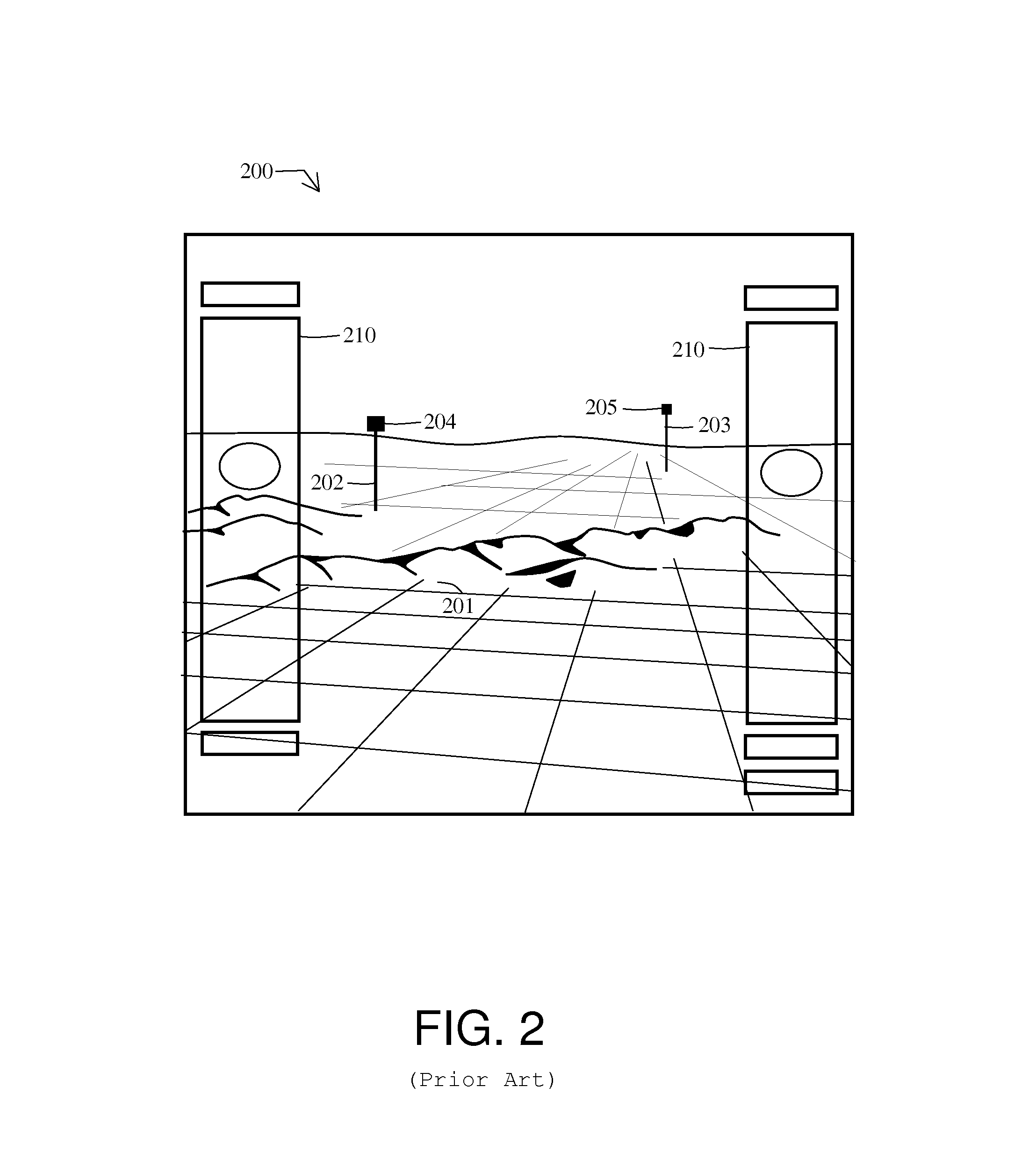
Although the new SVS systems give the pilot a better understanding of the situation of the intruders, in particular their type, their positioning, their behaviour, their performance, and so on, these new systems are inadequate for carrying out missions at low altitude.
This last configuration has already led to a large number of fatal accidents with the pilot choosing to climb and / or descend.

Method used


Image

  • Viewing device for aircraft comprising means of displaying trajectories of intruders presenting a risk of collision in all the space surrounding the aircraft
  • Viewing device for aircraft comprising means of displaying trajectories of intruders presenting a risk of collision in all the space surrounding the aircraft
  • Viewing device for aircraft comprising means of displaying trajectories of intruders presenting a risk of collision in all the space surrounding the aircraft

Examples


Embodiment Construction

[0034]FIG. 3 represents an exemplary architecture of the system, the subject of the invention, mounted on a first aircraft. The other aircraft situated in the space close to this first aircraft will be called hereinafter in the description intruding aircraft or more simply intruders.

[0035]This exemplary graphic display system 600 includes a processor 602 configured to supply the screen 606 with the information to be displayed. One or more data sources are linked to the processor 602. These data sources include a terrain database 604 used for plotting the perspective view, positioning sensors 603 of the aeroplane, air traffic detection systems, intrusion detectors 605 and control means 601 for the presentation of the information to the pilot.

[0036]These databases are generally positioned in the aircraft. The data can also originate from the ground by transmission or “data link” means. Furthermore, these data can be stored on different peripheral devices such as diskettes, hard disks,...


PUM


Abstract

A synthetic vision type viewing system SVS for a first aircraft includes at least position sensors of the first aircraft, a traffic detection system for calculating the position and the dangerousness of at least one second aircraft presenting a risk of collision with the first aircraft based on data obtained from sensors or from the TCAS or ADS-B, an electronic computer, a human-machine interface device and a display screen. The computer includes a processing unit configured to process different information obtained from the database, from the sensors and from the interface device. The processing unit is configured to provide the display screen with a synthetic image of the space surrounding the first aircraft and center on the latter. The image includes at least one first symbol of the first aircraft and a second representation of the past and present trajectory of the second aircraft.

Description

RELATED APPLICATIONS[0001]The present application is based on, and claims priority from, French Application Number 08 04949, filed Sep. 9, 2008, the disclosure is hereby incorporated by reference herein in its entirety.BACKGROUND OF THE INVENTION[0002]1. Field of the Invention[0003]The general field of the invention is that of anti-collision systems for aircraft and more particularly that of the presentation of anti-collision information.[0004]2. Description of the Prior Art[0005]For an aircraft in flight, it is vital to know very accurately the aircraft that are situated in its immediate environment in order to avoid any risk of collision. This problem is particularly crucial in a certain number of applications where the aircraft are required to fly at low altitude with possibly reduced visibility conditions. Historically, since the years 1960-1970, a solution that is independent of Air Traffic Control has gradually emerged. This solution is known by the acronym TCAS, standing for ...

Claims


Application Information

Patent Timeline
Patent Type & Authority Patents(United States)
IPC IPC(8): G06F17/10G01S13/935
CPCG01C23/00G08G5/0021G08G5/0078G08G5/045G01D2207/10
Inventor NOUVEL, CHRISTIANBACABARA, CORINNEPERBET, JEAN-NOEL
Owner THALES SA
Learn More