Broiler, conveyor oven, and toaster system with pressurized air guide for heat and flames

a conveyor oven and toaster technology, which is applied in the direction of gaseous heating fuel, stoves or ranges, heating types, etc., can solve the problems of uncomfortable environment for kitchen staff, energy-intensive equipment of conveyor ovens and broilers, etc., to facilitate waste heat transfer, increase energy efficiency, and save energy.

Active Publication Date: 2012-09-25
NIECO CORP
View PDF11 Cites 12 Cited by
  • Summary
  • Abstract
  • Description
  • Claims
  • Application Information

AI Technical Summary

Benefits of technology

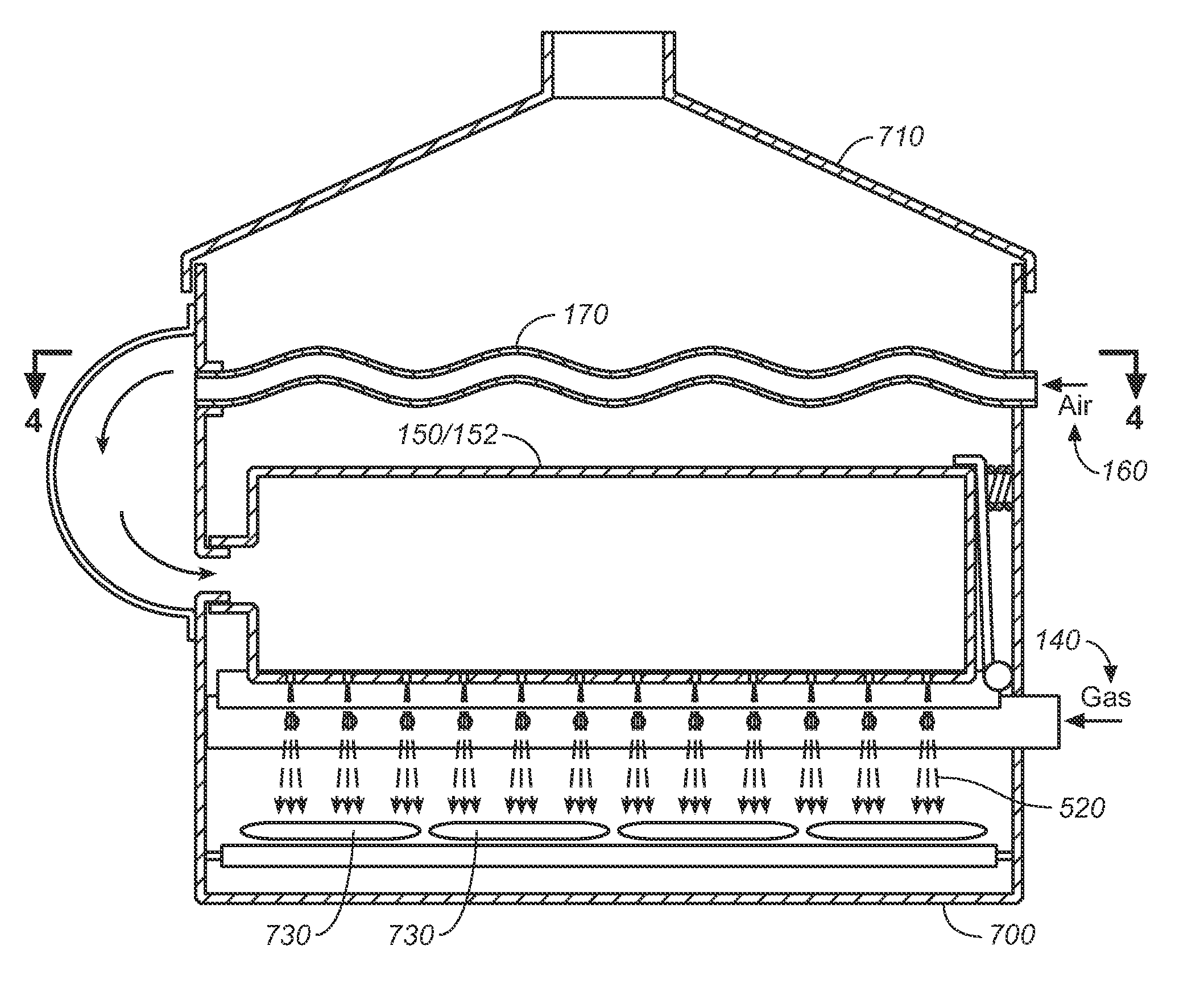
[0020]This unique design provides an efficient transfer of waste heat and energy from the heating source (heating elements and heat reflective structures) to the food products. The protective air curtain provided by the pressurized air system focuses and directs air heated by waste heat in a way that minimize heat loss from the cooking chamber. Significant energy savings is thereby realized.
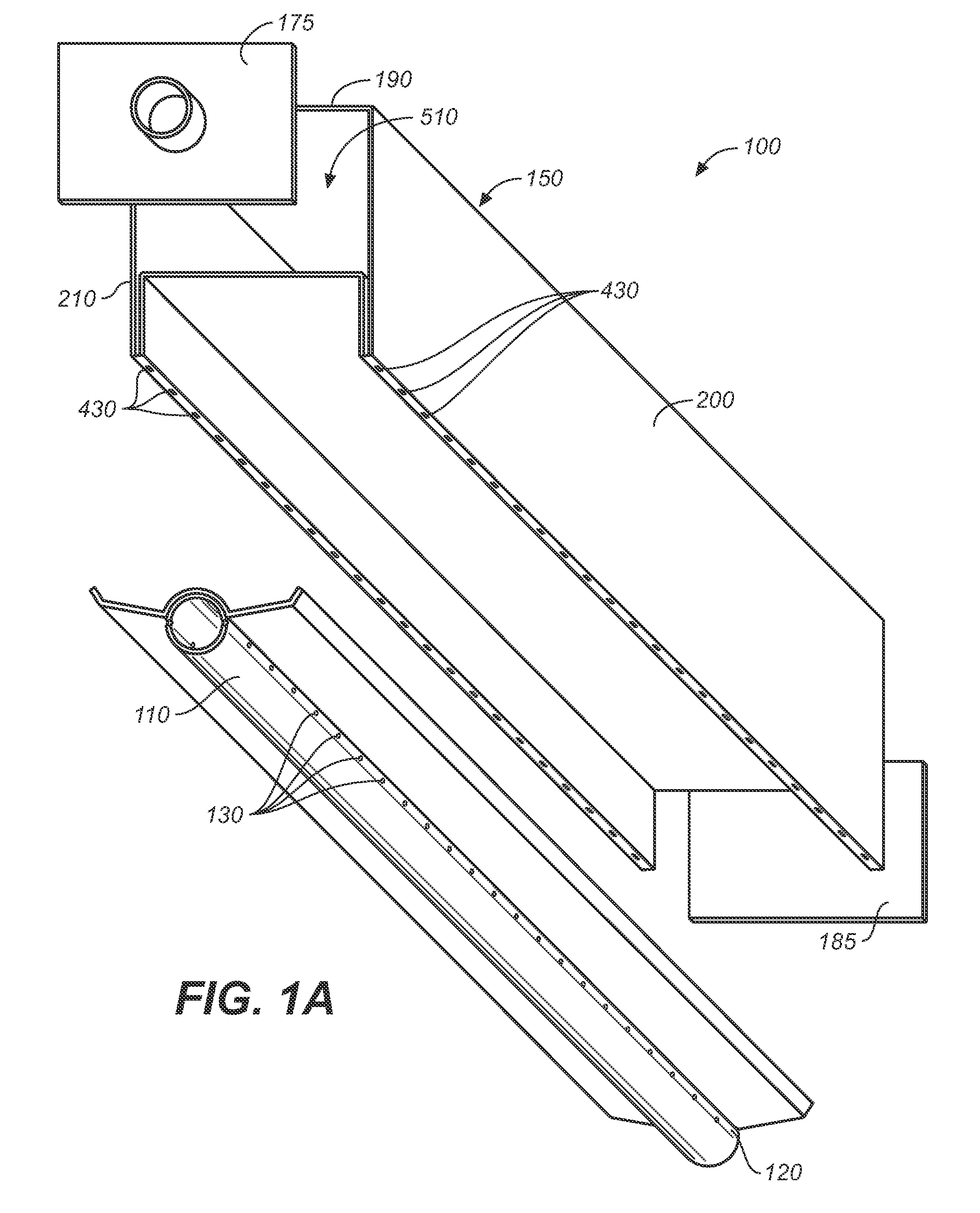
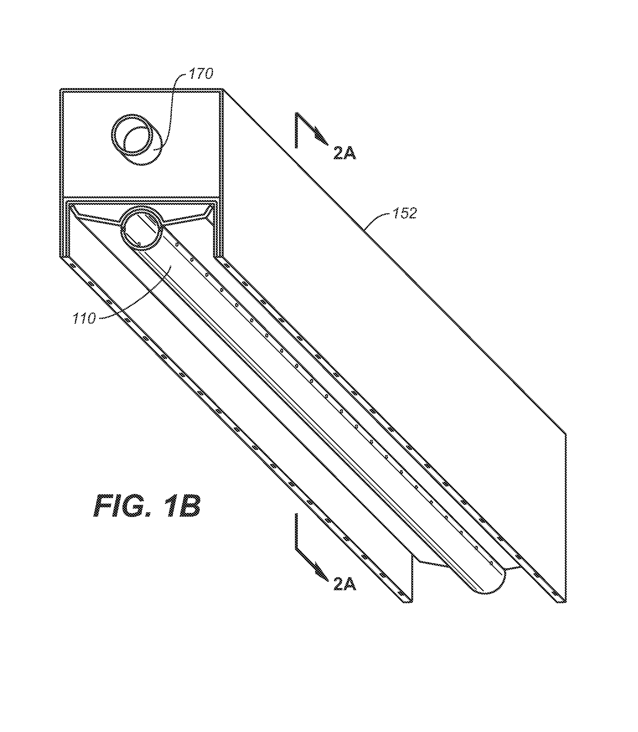
[0021]A first preferred embodiment of the inventive system includes a unit employing a gas burner element, in which there is provided a generally cylindrical gas pipe having gas outlets along the right and left sides of its entire length. The pipe may be any of a number of shapes and configurations, and when a conventional round pipe is used, the gas outlets are preferably disposed at roughly the 3 o'clock and 9 o'clock positions or the 4 o'clock and 8 o'clock positions, though it will be appreciated that the outlets may be oriented in any of a number of suitable positions, and there is no requirement that they be linearly aligned along the length of the burner or that they are provided along the entire length of the burner. An air plenum is disposed over the burner element substantially the entire length of the element, and pressurized air (i.e., higher than ambient pressure) is pumped into the plenum. In the first preferred embodiment, the plenum comprises an upper and a lower U-shaped channel which may be discrete and attached or either formed integrally, and it includes two arrays of air outlet nozzles either integrally formed within the plenum or comprising two L-shaped nozzle plates interposed between the lower and upper U-shaped channels at each side of the plenum. In either arrangement, the row or linear array of shaped orifices allow pressurized air to pass outwardly and downwardly from the plenum. In alternative embodiments, the plenum may be configured in shapes other than U-shaped to position air outlet nozzles on only one side of the heating element(s). The arrays are therefore disposed on either one or both sides of the heating element(s). In the case of gas burners, the air outlet nozzles are oriented in an array which is generally parallel to the gas orifices in the burner element. Each of the gas orifices may be matched with a proximate air orifice, though the match in number is not essential. The most important characteristic is that the air outlet array provide an effective air curtain to contain and direct heat. Accordingly, the inventive apparatus provides pressurized air that passes through the air orifices in thin jets from the plenum and around the gas flames. Thus, the heat from the flames, as well as the flames themselves, are directed downwardly toward the food product by the moving air streams. When used to cook food products, the hot air moved in this fashion breaks up the water vapor envelope that typically covers and insulates the food product as it initially thaws and / or evaporates water and begins heating. When used with thawed food product, the hot air evaporates water and begins heating. This use of hot air facilitates faster cooking and enhances browning. The air also facilitates complete oxidation of the gas fuel, thereby increasing efficiency, saving on energy costs, and reducing pollution. The air jets will help the heat penetrate the food product to improve heating of interior portions of the food.
[0025]The size of the air plenum is significant for sustained heat recovery of a cooking system during high load / high quality cooking The larger the air plenum, the easier it is for a cooking system to recover.
[0027]An air plenum may also use re-circulated heated air. In this case, heated air would be taken from the cooking chamber and then returned to the air plenum via an air blower or venturi heat-inducing system for increased energy efficiency.
[0029]The orifices of the air plenum for the air jets can also be used to introduce sear marks or other random or unique pattern dark markings on the food. Alternatively, distinctive sear or dark marks can be eliminated by different configuration of the orifice holes and air pressure adjustment.
[0030]In yet another preferred embodiment an air-to-air waste heat recovery system can be incorporated into a conveyor broiler assembly, or into oven or toaster assemblies. The system achieves unexpected energy savings by utilizing waste heat from the radiant heat source and utilizes it to pre-heat air in a low pressure air system before the air is directed in a focused curtain down onto food product conveyed through the cooking chamber. A blower provides the supply of pressurized fresh air to a first heat transfer pipe that traverses the upper portion of the cooking chamber and enters a first air plenum box mounted the upper cooking chamber walls. Air passes through air outlets disposed at the lower ends of the wings that extend down from the plenum and angle inwardly toward the center of the cooking chamber. A second heat transfer pipe connects the first air plenum to a second air plenum, configured in a similar manner. A cap is disposed immediately above the top sides of the air plenums and serves to confine rising hot air, temporarily capturing it in the air space between the air plenums and occupied by the heat transfer pipes. The hot air is retained in that space until its volume and kinetic energy are sufficient to have it spill outside the footprint of the air plenums and rise past them where it is vented outside. The cooperating elements form a baffle system that facilitates the transfer of waste heat from hot cooking chamber air to the air in the forced air system, such that the focused curtain of forced air directed downwardly at food product is between 450° and 850° F.

Problems solved by technology

Present day conveyor oven and broiler designs are energy intensive equipment, not only in their direct consumption of electricity and / or natural gas, but also due to the load they place on HVAC systems due to waste.
Ovens and broilers call for high exhaust flow rates and create high temperatures in the often small space provided in the kitchen area, creating an uncomfortable environment for kitchen staff.

Method used


Image

  • Broiler, conveyor oven, and toaster system with pressurized air guide for heat and flames
  • Broiler, conveyor oven, and toaster system with pressurized air guide for heat and flames
  • Broiler, conveyor oven, and toaster system with pressurized air guide for heat and flames

Examples


example 1

[0103]In a first test, the Nieco 624 gas conveyor broiler, which is a standard platform for a first major fast food restaurant chain (Chain X, name withheld), was compared to a newer system, the JF62 gas conveyor broiler, which was modified to incorporate the inventive waste heat recovery system. The Nieco 624 gas conveyor broiler is a standard pass-through design with a single chain running through the cooking chamber that accommodates three cooking lanes for product (e.g., hamburger patties), three rows deep. A catch tray at the end of the conveyor collects the cooked product. In operation in typical franchise establishment, the conveyor runs continuously during the day, with the heat source constantly energized. The broiler uses infrared gas burners to heat the broiling chamber and electric motors to drive the conveyor through the chamber. A secondary chain runs beneath the main cooking chamber with electrically-heated platens for toasting buns.

[0104]The new JF62 conveyor broiler...

example 2

[0128]In second and third tests, a Nieco 1424 gas conveyor broiler (with no catalyst), and a Nieco 1424 gas conveyor broiler (with catalyst) were compared to a new Nieco JF143 gas conveyor broiler with catalyst.

[0129]Background: In recent years, conveyor broilers have fallen under mandates by regional Air Quality Management Districts (AQMDs) in the state of California. These AQMDs require conveyor broilers to have an added catalyst to reduce the particulate emissions from cooking meats. The catalyst fits on top of the broiler cooking chamber and converts captured grease into carbon dioxide and water vapor. Testing has shown that the use of a catalyst can reduce the energy consumption of the conveyor broiler by reflecting heat back into the cooking chamber.

[0130]The Nieco 1424 gas conveyor broiler is the existing standard cooking platform in two major fast food restaurant chains, Chain Y and Chain Z [actual names withheld as confidential]. As with the 624 conveyor broiler, the 1424 b...


PUM


Abstract

A cooking apparatus having a waste heat recovery system for incorporation into broilers, ovens, and toasters, the apparatus including a cooking chamber having a cooking platform, at least one air plenum disposed in the upper portion of the cooking chamber and having a plurality of air outlets for producing a focused forced air, a low pressure air source connected to the air plenums, a heating element or burner disposed under each of said air plenums, such that said curtain of focused forced air guides and directs heat from said heating element toward food product being cooked, and heat exchange pipes disposed between at least two of said air plenums. Radiant heat generated from the heating elements or burners rises in the cooking chamber and is retained between the air plenums to maximize heat transfer from the heated air to the heat transfer pipes, and thus to the low pressure air in the low pressure air system. The recycled heat enhances cooking.

Description

CROSS REFERENCES TO RELATED APPLICATIONS[0001]The present application is a continuation-in-part of U.S. Continuation-in-Part patent application Ser. No. 12 / 410,012, filed (Mar. 24, 2009) now abandoned, which is a continuation in part of U.S. Utility patent application Ser. No. 11 / 849,854, filed (Sep. 4, 2007) now U.S. Pat. 7,997,189, which in turn claims the benefit of the filing date of U.S. Provisional Patent Application Ser. No. 60 / 824,419, filed (Sep. 1, 2006), and further claims the benefit of the filing date of U.S. Provisional Patent Application 61 / 144,693, filed (Jan. 14, 2009).STATEMENT REGARDING FEDERALLY SPONSORED RESEARCH OR DEVELOPMENT[0002]Not applicable.THE NAMES OR PARTIES TO A JOINT RESEARCH AGREEMENT[0003]Not applicable.INCORPORATION-BY-REFERENCE OF MATERIAL SUBMITTED ON A COMPACT DISC[0004]Not applicable.SEQUENCE LISTING[0005]Not applicable.BACKGROUND OF THE INVENTION[0006]1. Field of the Invention[0007]The present invention relates generally togas burners and ele...

Claims


Application Information

Patent Timeline
Patent Type & Authority Patents(United States)
IPC IPC(8): A47J37/04A47J37/06
CPCA21B1/245A47J36/38A47J37/044A47J37/0682Y02P60/80
Inventor BAKER, EDWARDBAKER, MATTHEWBAKER, PATRICKMAGNER, ERIK
Owner NIECO CORP
Why Eureka
Try Eureka