Dual fuel connector

a fuel connector and connector technology, applied in the direction of fuel injection apparatus, mechanical equipment, jet propulsion plants, etc., can solve the problems of increasing the cost of conventional fuel engines, and spatial limitations of piping and the connection between the fuel rails, so as to facilitate installation and removal, improve engine performance and combustion efficiency, and simplify the piping to the fuel injection valve

Active Publication Date: 2012-09-25
WESTPORT FUEL SYST CANADA INC
View PDF41 Cites 33 Cited by
  • Summary
  • Abstract
  • Description
  • Claims
  • Application Information

AI Technical Summary

Benefits of technology

[0009]A dual fuel connector is disclosed for separately supplying two different fuels to a fuel injection valve, namely a first fuel that is supplied to a first fuel inlet into the fuel injection valve and a second fuel that is supplied to a second fuel inlet into the fuel injection valve. The dual fuel connector comprises a body with separate fluid connections to the first fuel inlet, the second fuel inlet, a first fuel rail and a second fuel rail. A first fuel passage within the body is in fluid communication with the first fuel rail and the first fuel inlet. A second fuel passage within the body is in fluid communication with the second fuel rail and the second fuel inlet. The first fuel passage is fluidly isolated from the second fuel passage. Accordingly, the dual fuel connector simplifies piping to the fuel injection valve from the fuel rails by eliminating the need for connections from the two fuel rails directly to the fuel injection valve, and this also facilitates installation and removal of the fuel injection valve since the connections between the fuel rails and the dual fuel connector do not need to be undone when installing or removing the fuel injection valve. By delivering the two fuels to the fuel injection valve separately, the disclosed dual fuel connector also allows the possibility of improving engine performance and combustion efficiency by permitting greater flexibility in controlling the proportion of each fuel that is delivered to the combustion chamber and the timing for introducing each fuel into the combustion chamber, depending upon the capabilities of the fuel injection valve.
[0010]In a preferred embodiment the body of the dual fuel connector is elongated with a proximal end associated with the fuel injection valve and a distal end associated with the first and second fuel rails. In some embodiments the elongated body of the dual fuel connector is mountable in a first bore provided in the cylinder head that intersects with a second bore provided in the cylinder head in which the fuel injection valve is mountable. The body can comprise a central bore that defines the first fuel passage and the second fuel passage can be defined by an annular space around the central bore with a wall separating the first and second fluid passages, and in such embodiments the wall separating the first and second fluid passages can be tubular. An advantage of an arrangement with concentric fluid passages is that while the wall separating the first and second fluid passages is made with a thickness that is selected to withstand differential pressures between the first fuel and the second fuel without rupturing or deflecting to a degree that the flow of the first or second fuels is affected, this thickness can be less than what is needed to withstand rupture against a designed maximum gauge pressure of the second fuel. This is because the differential pressure acting on the wall is much less than the gauge pressure of either one of the two fuels, so the separating wall is not subjected to the entire gauge pressure. Accordingly, the disclosed arrangement with concentric fluid passages can allow the separating wall to be thinner, which can allow the overall cross sectional diameter of the dual fuel connector to be smaller.
[0011]In a preferred embodiment the first fuel is a gaseous fuel and the second fuel is a liquid fuel. Compared to the liquid fuel, the gaseous fuel can be a cleaner burning fuel that does not ignite as easily as the liquid fuel. By burning mostly gaseous fuel, engine emissions can be improved and a small amount of liquid fuel can be injected to assist with at least one of cooling, lubrication within the fuel injection valve, and ignition of the gaseous fuel.

Problems solved by technology

Recent increases in global oil prices make conventionally fuelled engines more costly to operate.
A challenge associated with this approach is that it requires the supply of two different fuels to the fuel injection valves.
However, unlike the model ISX engine, many other engines are designed to use external piping for supplying fuel to the fuel injection valves so they do not have bores provided within their cylinder heads that can serve as fuel rails.
For these engines a problem with delivering two fuels to fuel injection valves using external piping is that the additional piping associated with the second fuel rail adds complexity and there are spatial limitations for the piping and the connections between the fuel rail and the fuel injection valves.

Method used


Image

  • Dual fuel connector
  • Dual fuel connector
  • Dual fuel connector

Examples


Embodiment Construction

)

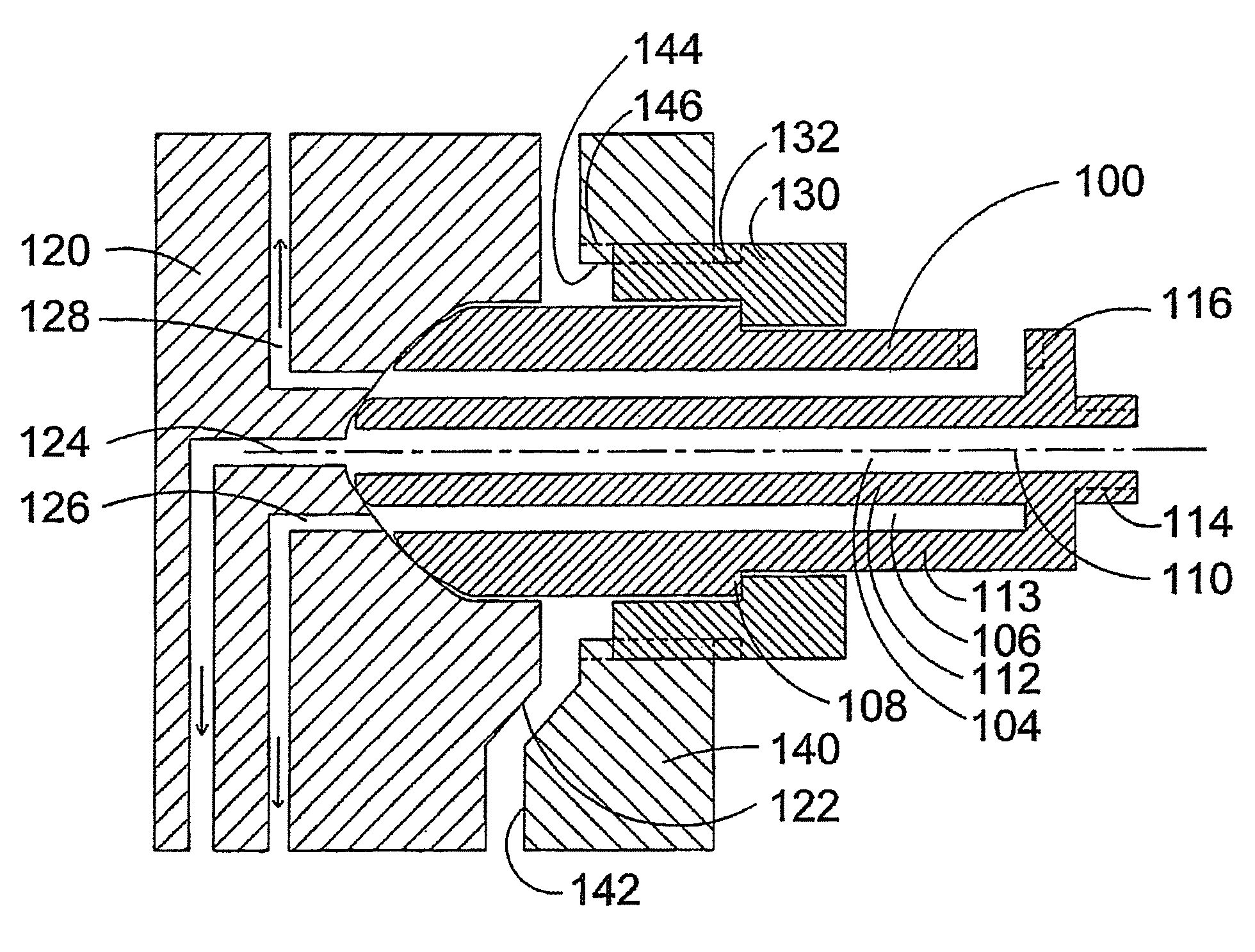
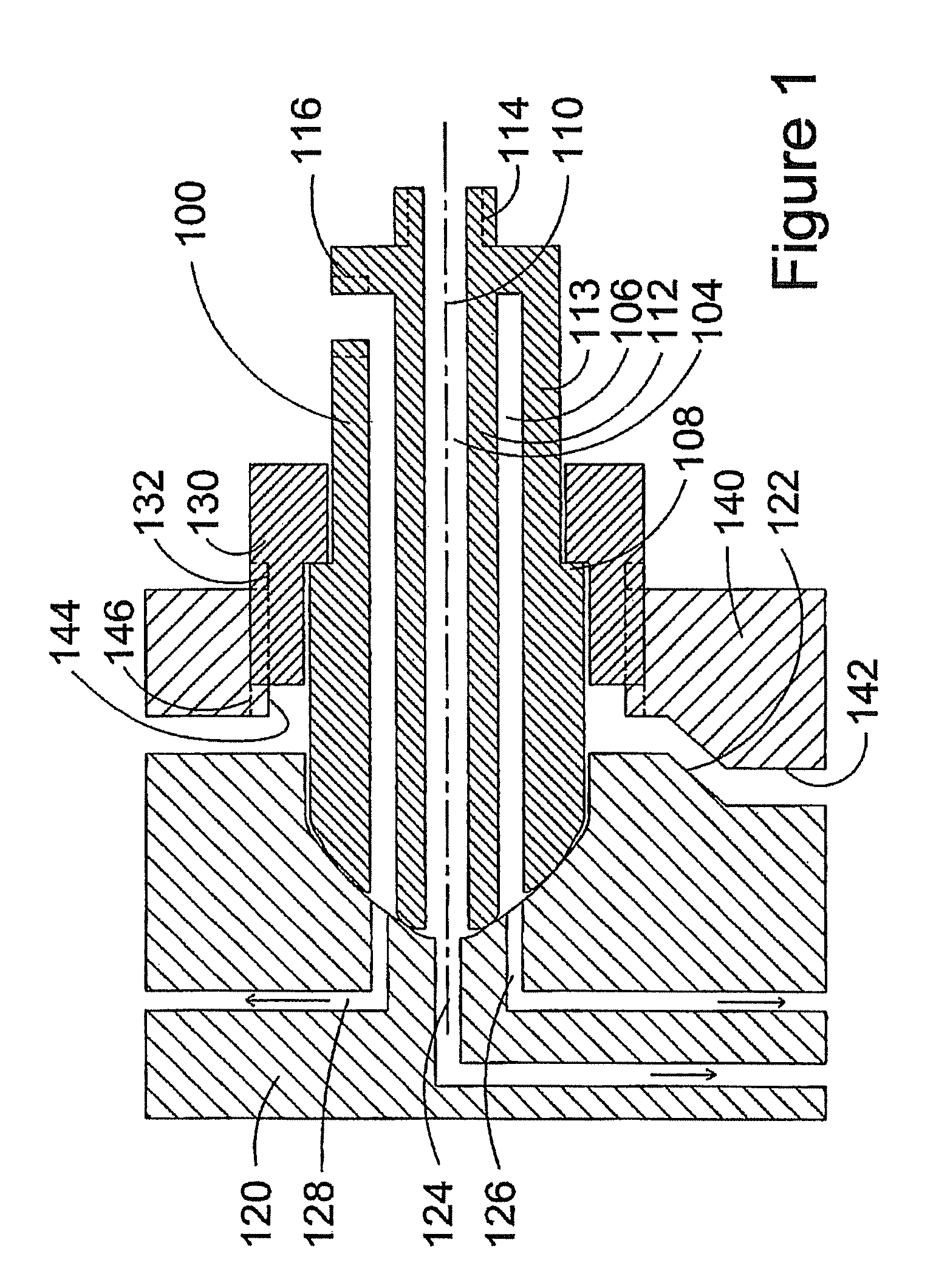
[0030]FIG. 1 shows a cross section side view of dual fuel connector 100 and a partial section view of fuel injection valve 120 at a location where the proximal end of dual fuel connector 100 is sealable against it. Common to all embodiments, dual fuel connector 100 comprises one body that provides first fuel passage 104 and second fuel passage 106 for separately delivering two different fuels to fuel injection valve 120. A central bore through the body of dual fuel connector 100 defines first fuel passage 104 and an annual space between separating wall 112 and outside wall 112 defines second fuel passage 106. Accordingly, separating wall 112, which is generally cylindrical and hollow in shape separates first fuel passage 104 from second fuel passage 106. An advantage of this arrangement is that separating wall 112 need only be designed to withstand the differential pressure between the two fuels and the compressive force transmitted through the body to seal against fuel injection v...


PUM


Abstract

A dual fuel connector separately supplies two different fuels to fluidly isolated fuel passages within a fuel injection valve of an internal combustion engine. The dual fuel connector comprises a body with separate fluid connections to the first fuel inlet, the second fuel inlet, a first fuel rail and a second fuel rail. A first fuel passage within the body is in fluid communication with the first fuel rail and the first fuel inlet. A second fuel passage within the body is in fluid communication with the second fuel rail and the second fuel inlet, and wherein the first fuel passage is fluidly isolated from the second fuel passage. The dual fuel connector supplies two different fuels to a fuel injection valve, for engines that are not designed with a cylinder head that has internal bores that can serve as fuel rails.

Description

CROSS-REFERENCE TO RELATED APPLICATION(S)[0001]This application is a continuation of International Application No. PCT / CA2009 / 000591, having an international filing date of Apr. 30, 2009, entitled “Dual Fuel Connector”. The '591 international application claimed priority benefits, in turn, from Canadian Patent Application No. 2,635,410 filed Jun. 19, 2008. The '591 international application is hereby incorporated by reference herein in its entirety.FIELD OF THE INVENTION[0002]The present invention relates to a dual fuel connector for supplying two different fuels to separate fuel passages in a fuel injection valve for an internal combustion engine. The invention is particularly suited to an arrangement where the two fuels are each supplied under high pressure and the fuel injection valve is located within a first bore provided in an engine cylinder head with the dual fuel connector located within a second bore provided in the engine cylinder head with the second bore intersecting wi...

Claims


Application Information

Patent Timeline
Patent Type & Authority Patents(United States)
IPC IPC(8): F02M55/02
CPCF02D19/08F02M43/00F02M43/04F02D19/0694F02D19/0642F02D19/0676F02D19/0689F02M55/005Y02T10/36F02M63/029Y10T137/0402Y02T10/30
Inventor WICKSTONE, MICHAEL C.
Owner WESTPORT FUEL SYST CANADA INC
Why Eureka
Try Eureka