Dual electromagnetic valve and evaporated gas treatment system
a technology of electromagnetic valves and evaporated gas, applied in the direction of valve operating means/release devices, combustion air/fuel air treatment, machines/engines, etc., can solve the problems of unfavorable pressure loss, reduced flow rate, and inability to make full use of the control capability (control flow rate) of each individual electromagnetic valv
- Summary
- Abstract
- Description
- Claims
- Application Information
AI Technical Summary
Benefits of technology
Problems solved by technology
Method used
Image
Examples
embodiment 1
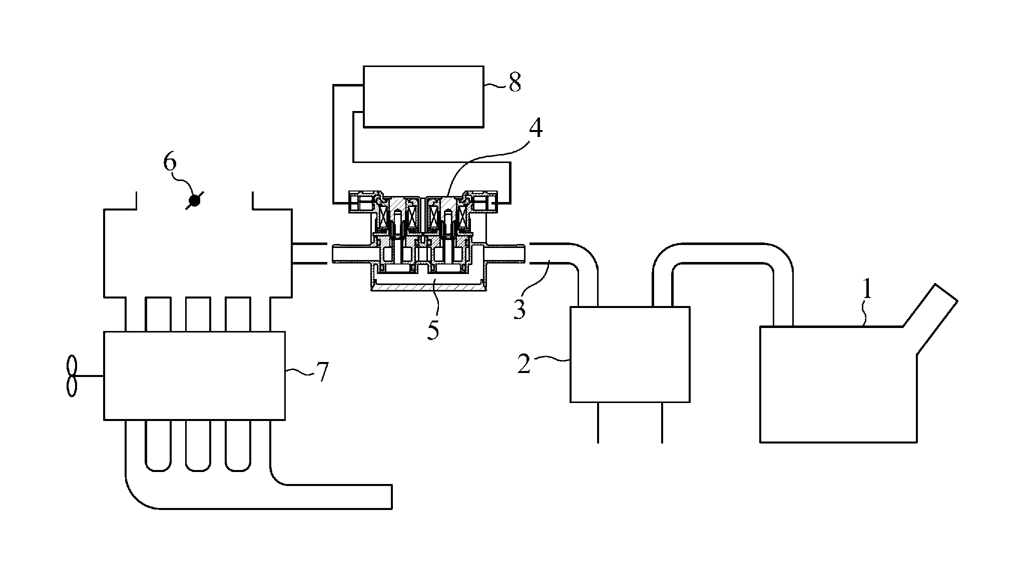
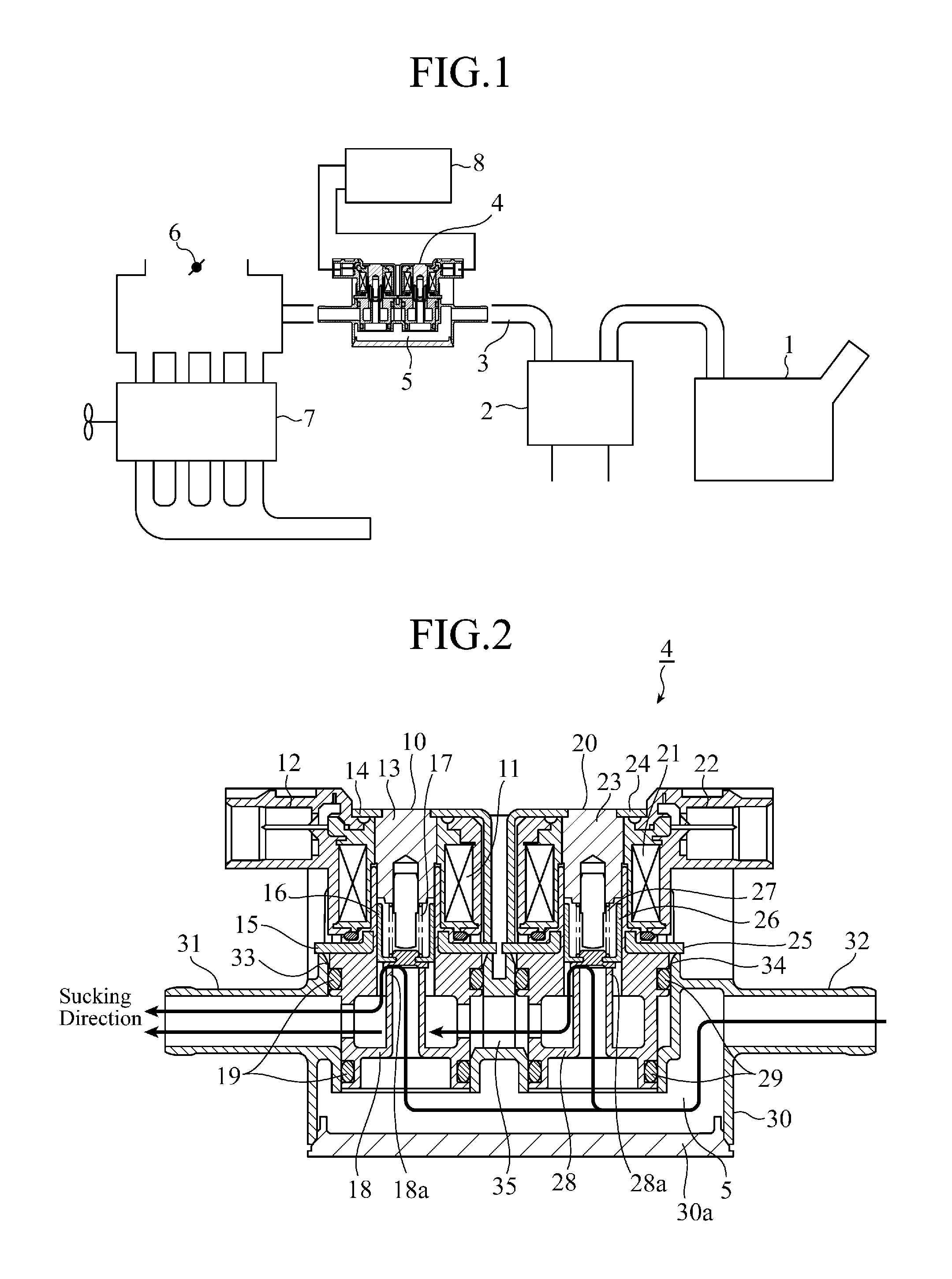
[0027]In an evaporated gas treatment system shown in FIG. 1, the evaporated gas volatilized in a fuel tank 1 is temporarily collected in a canister 2; through the use of the negative pressure produced in an engine 7, the evaporated gas is sucked from the canister 2 into the engine 7 for recombustion, thereby to be prevented from being discharged to the outside. In a suction path 3 connecting the canister 2 and the engine 7, a dual electromagnetic valve 4 integrated with a chamber 5 is arranged, and controls the amount of the evaporated gas in response to a driving signal from a control unit 8.
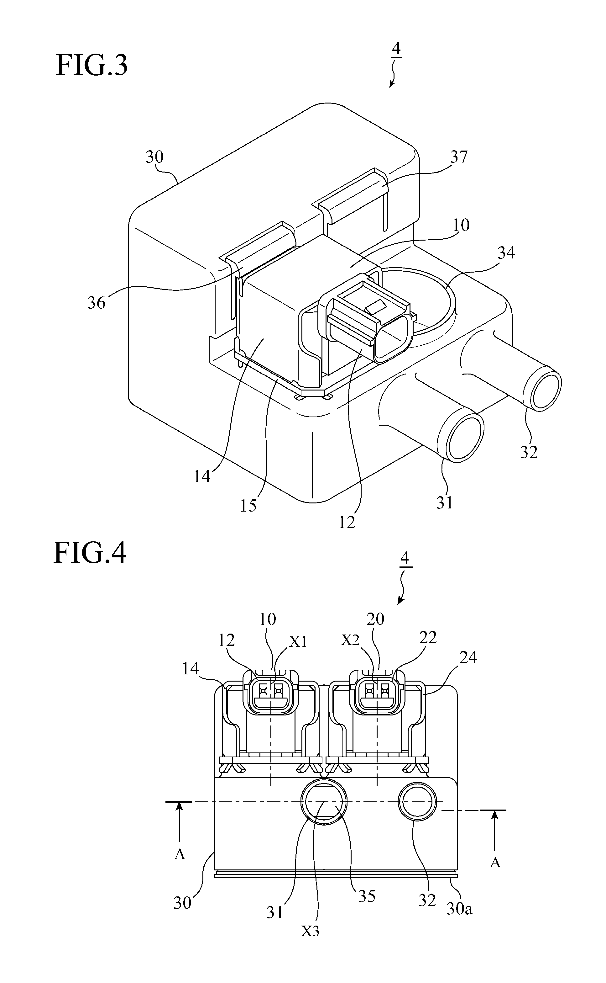
[0028]FIG. 2 is a longitudinal cross-sectional view showing the configuration of the dual electromagnetic valve 4. The dual electromagnetic valve 4 includes: a housing 30 composed of a suction port 31, a discharge port 32, and a chamber 5 communicating with the ports; a pair of electromagnetic valves 10 and 20 having tubular flow paths (flow path parts) 18 and 28 inserted into the chamber 5, an...
embodiment 2
[0064]In the above Embodiment 1, both the first electromagnetic valve 10 and the second electromagnetic valve 20 are provided in the reverse suction mode, but may also be provided in different suction modes.
[0065]FIG. 10 shows a configuration example of the dual electromagnetic valve 4 in which the suction modes of the first electromagnetic valve 10 and the second electromagnetic valve 20 are constituted differently. It is noted that the parts in FIG. 10 equal to or equivalent to those of FIGS. 2 to 6 are denoted by the same reference numerals and signs, and explanations thereof will be omitted.
[0066]In the present Embodiment 2, the first electromagnetic valve 10 is provided in the reverse suction mode in which the negative pressure application direction is equal to the valve opening direction of the plunger 16, and the negative pressure acts in the valve opening direction, while the second electromagnetic valve 20 is provided in the positive suction mode in which the negative press...
PUM
 Abstract
Description
Claims
Application Information
 - R&D
- Intellectual Property
- Life Sciences
- Materials
- Tech Scout
- Unparalleled Data Quality
- Higher Quality Content
- 60% Fewer Hallucinations
Browse by: Latest US Patents, China's latest patents, Technical Efficacy Thesaurus, Application Domain, Technology Topic, Popular Technical Reports.
© 2025 PatSnap. All rights reserved.Legal|Privacy policy|Modern Slavery Act Transparency Statement|Sitemap|About US| Contact US: help@patsnap.com


