
Ion-exchange membrane electrolysis device

a technology of ion exchange membrane and electrolysis device, which is applied in the direction of electrolysis components, other medical devices, respirators, etc., can solve the problems of troublesome wiring assembly, high cost, cumbersome procedures, etc., and achieve the effect of reducing the volume reducing manufacturing cost, and improving the operation safety of the ion exchange membrane electrolysis devi

Active Publication Date: 2020-01-16
LIN HSIN YUNG
View PDF0 Cites 0 Cited by
  • Summary
  • Abstract
  • Description
  • Claims
  • Application Information

AI Technical Summary

Benefits of technology

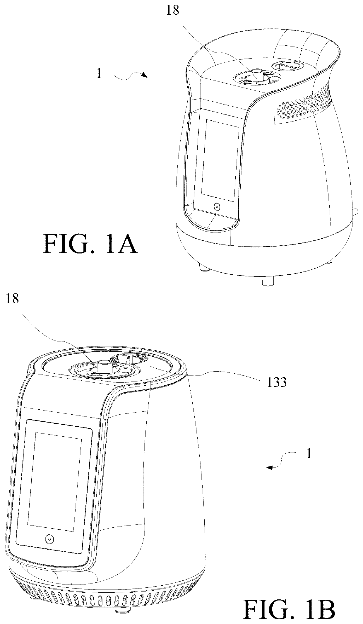
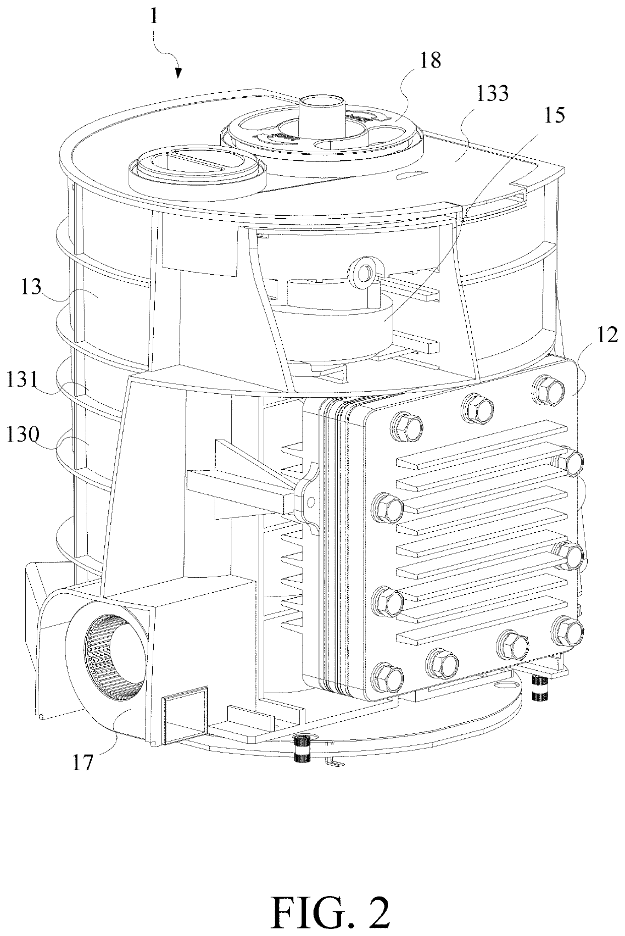
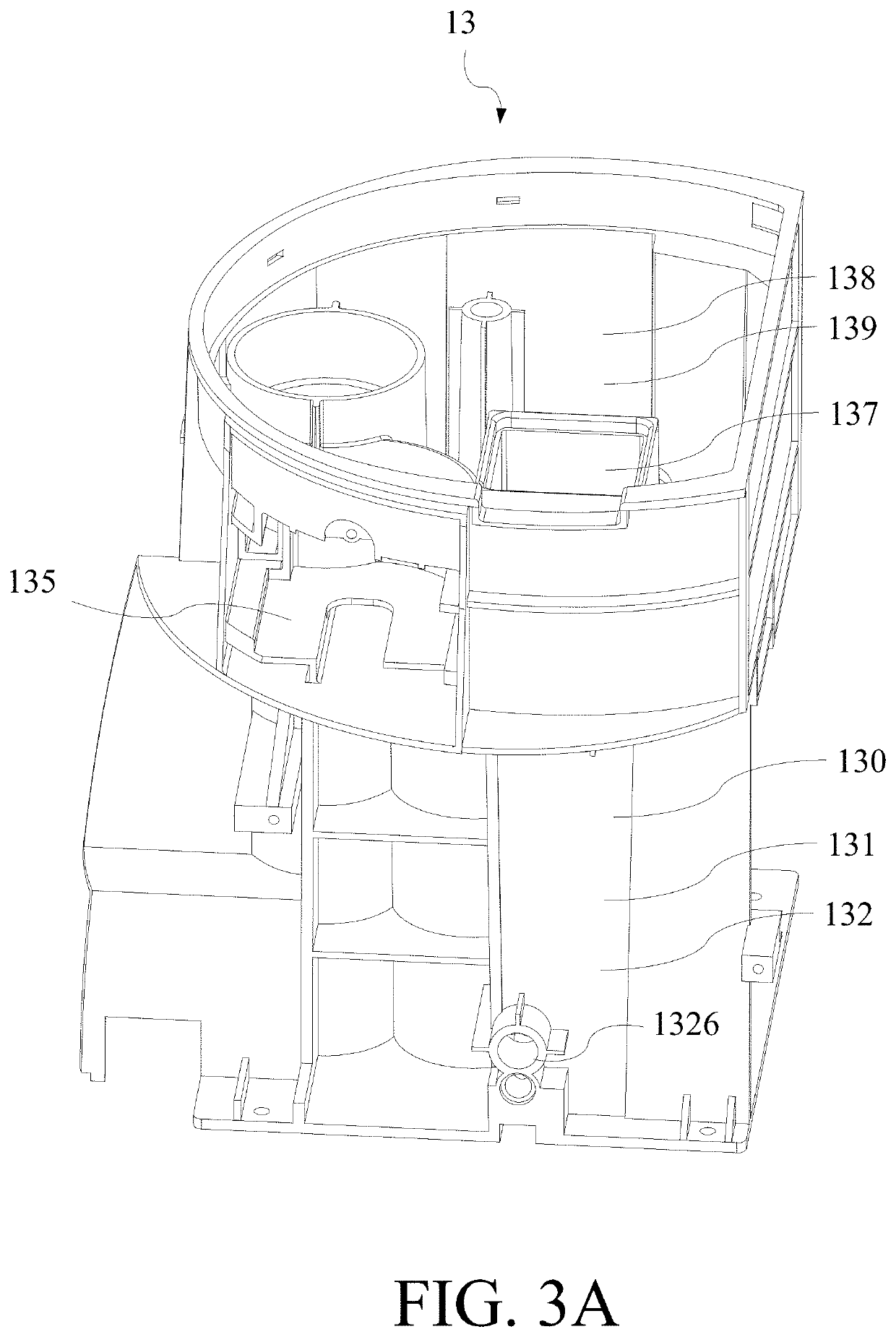
The present invention provides an integrated ion membrane electrolysis device that merges pipelines into a single flow channel device, reducing the volume and manufacturing cost of the device while improving safety. The device has a gas flow channel system and a water flow channel system that transport hydrogen and water between devices without the need for additional tubes. The arrangement of reserved spaces allows for the attachment of other devices, such as an ion-exchange membrane electrolysis cell, a filter, a nebulizer, and a gas supplement fan. Overall, the integrated flow channel device simplifies piping, reduces cost, and improves operational safety.

Problems solved by technology

However, in the prior art, the pipelines between devices need to be assembled separately, which causes cumbersome procedures, troublesome wiring assembly, high cost, difficulty in standardization, difficulty in shrinking the volume, and even the falling-off of the flow channel and water leaks in use.

Method used


Image

  • Ion-exchange membrane electrolysis device
  • Ion-exchange membrane electrolysis device
  • Ion-exchange membrane electrolysis device

Examples


Embodiment Construction

[0046]A detailed description of the hereinafter described embodiments of the disclosed apparatus and method are presented herein by way of exemplification and not limitation with reference to the Figures. Although certain embodiments are shown and described in detail, it should be understood that various changes and modifications can be made without departing from the scope of the appended claims. The scope of the present invention will in no way be limited to the number of constituting components, the materials thereof, the shapes thereof, the relative arrangement thereof, etc., and are disclosed simply as an example of embodiments of the present invention.

[0047]In the description of the present specification, the terminologies “in an embodiment”, “in another embodiment”, or “in some embodiments” means that the specific feature, structure, material or characteristic of the present embodiment is involved in at least one embodiment of the present invention. In the description of the ...


PUM


Abstract

An ion-exchange membrane electrolysis device includes an ion-exchange membrane electrolytic cell and an integrally formed integrated flow channel device. The ion-exchange membrane electrolytic cell generates a gas comprising hydrogen. The integrated flow channel device has a first setting structure, a water tank structure, a gas flow channel system and a water flow channel system. The water tank structure accommodates water. The first setting structure is configured for removably fixing the ion-exchange membrane electrolytic cell to the integrated flow channel device. The water flow channel system connects the water tank structure and the first setting structure for inputting the water in the water tank structure into the ion-exchange membrane electrolytic cell. The gas flow channel system is connected to the first setting structure for receiving and transporting the gas comprising hydrogen. Therefore, the present invention integrates functionally independent pathways, decreases pipeline connections, reduces volume of device, and improves safety of operation.

Description

[0001]The present application is based on, and claims priority from, China publication number CN108950588A, filed on 2018 Jul. 10, the disclosure of which is hereby incorporated by reference herein in its entirety.BACKGROUND OF THE INVENTIONField of the Invention[0002]The present invention provides an ion-exchange membrane electrolysis device, and more particularly, to an ion-exchange membrane electrolysis device comprising an integrated flow channel device formed integrally for reducing volume, reducing connections of the tubes, and improving safety.Description of the Prior Art[0003]For long time, people have paid much attention on human life. Many medical technologies have been developed to fight disease and extend human life, but most medical treatments in the past are passive. That is to say, the disease is treated when it occurs, such as surgery, drug administration, chemotherapy and radiotherapy of the cancer, or nursery, rehabilitation, and correction of the chronic disease. ...

Claims


Application Information

Patent Timeline
IPC IPC(8): C25B1/10C25B9/10C25B15/08A61M16/10A61K9/00A61K33/00C25B9/19C25B9/23
CPCA61K9/007A61M2202/02A61K33/00C25B9/10C25B15/08C25B1/10A61M16/10C25B9/00C25B1/04C25B9/73Y02E60/36A61M15/0003A61M15/0005C25B9/23A61M11/005A61M16/125
Inventor LIN, HSIN-YUNG
Owner LIN HSIN YUNG
Learn More