
Multi-function surface treatment tool

a surface treatment and multi-functional technology, applied in the direction of medical applicators, liquid dispensing, board cleaning devices, etc., can solve the problem of becoming impractical to hand hold a larger stuff container

Inactive Publication Date: 2012-09-25
LINZELL GEOFFREY ROBERT
View PDF25 Cites 11 Cited by
  • Summary
  • Abstract
  • Description
  • Claims
  • Application Information

AI Technical Summary

Benefits of technology

"The patent describes a tool that can be used to rub surfaces with a stuff dispenser to apply treatment. The tool has a stiff spined portion with lateral finlike protrusions that can hold the stuff and a rubbing capability provided by the underface of the protrusions. It also has a wiping capability provided by the face of the spine. The technical effect of this tool is that it allows for efficient and effective treatment of surfaces by rubbing and wiping residues off."

Problems solved by technology

The problem is the inconvenience caused by the number of actions and items required to treat and clean a surface, the effort involved and risks associated with repeated exposure of hands to chemicals.
Thus the problem to be solved is the design of a Tool, a multi-function Tool for treating and cleaning surfaces by rubbing, the Tool able to follow complex shapes and reach into recesses as it treats the surface by applying and spreading stuff, then agitating the stuff to maximise its effect, then removing residues and finally wiping the surface dry and clean while keeping hands safely removed clean and dry.
It may become impractical to hand hold a larger stuff container, therefore a stand alone stuff container is used joined by flexible hoses to the Tool mounted on a hand held dispenser head.

Method used


Image

  • Multi-function surface treatment tool
  • Multi-function surface treatment tool
  • Multi-function surface treatment tool

Examples


example 2

Means of Incorporating Dispensers Into Small Tools

[0113]Small Tools are small enough to be held and gripped by fingers during use and therefore it is often convenient to incorporate the dispenser into the Tool itself. On the other hand pencil shaped dispensers or slender pump like bodies, for example like those used with hypodermic needles can also be used with small Tools and these pencil Tools are attached or joined onto the Tool externally, in which case the attached dispenser may be used to hold the small Tool during use. By way of example three ways of incorporating dispensers into small Tools are now shown.

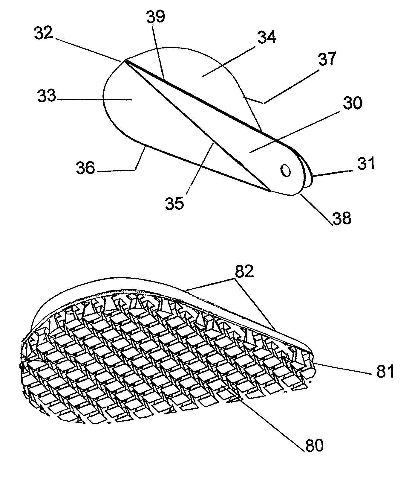
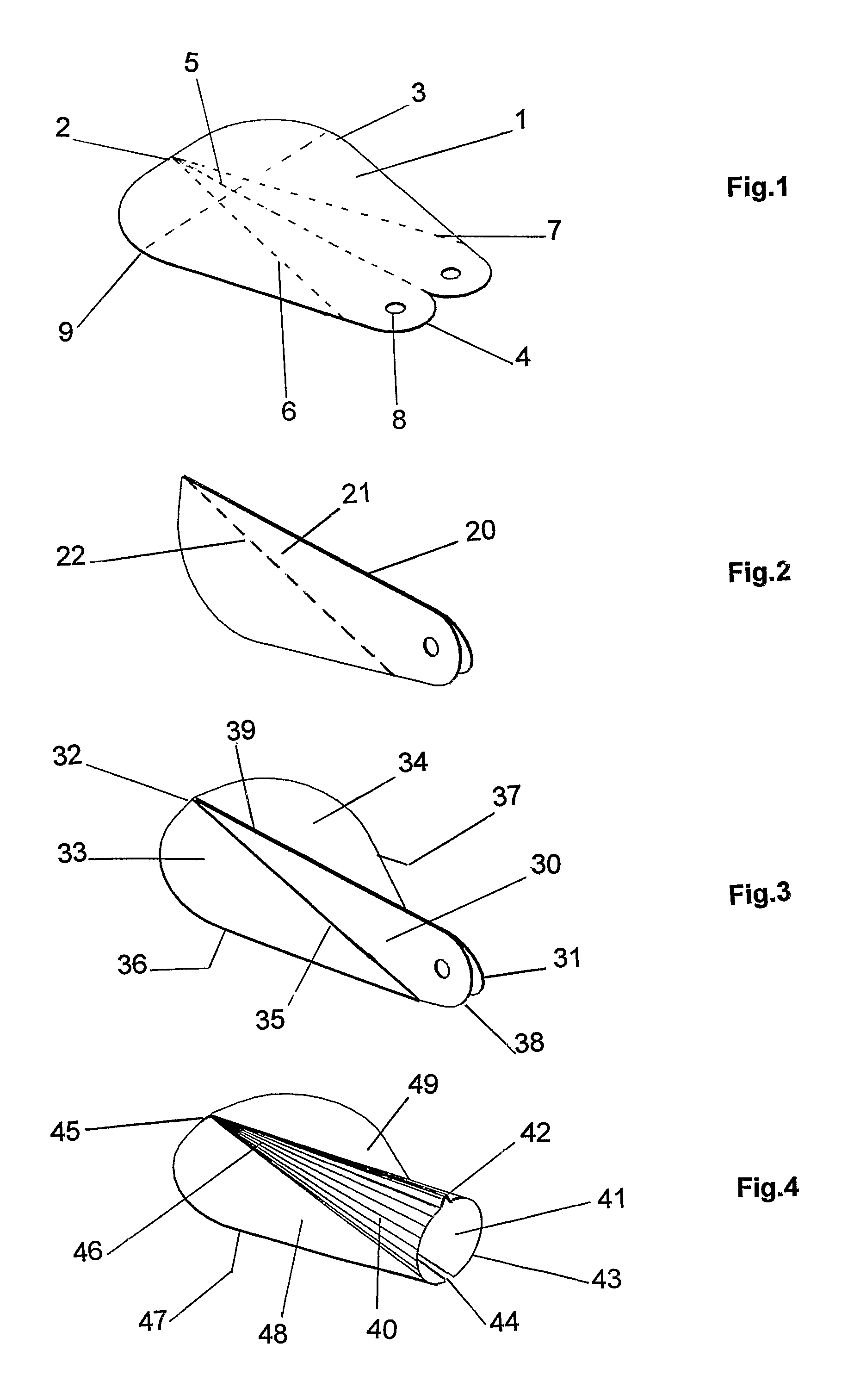
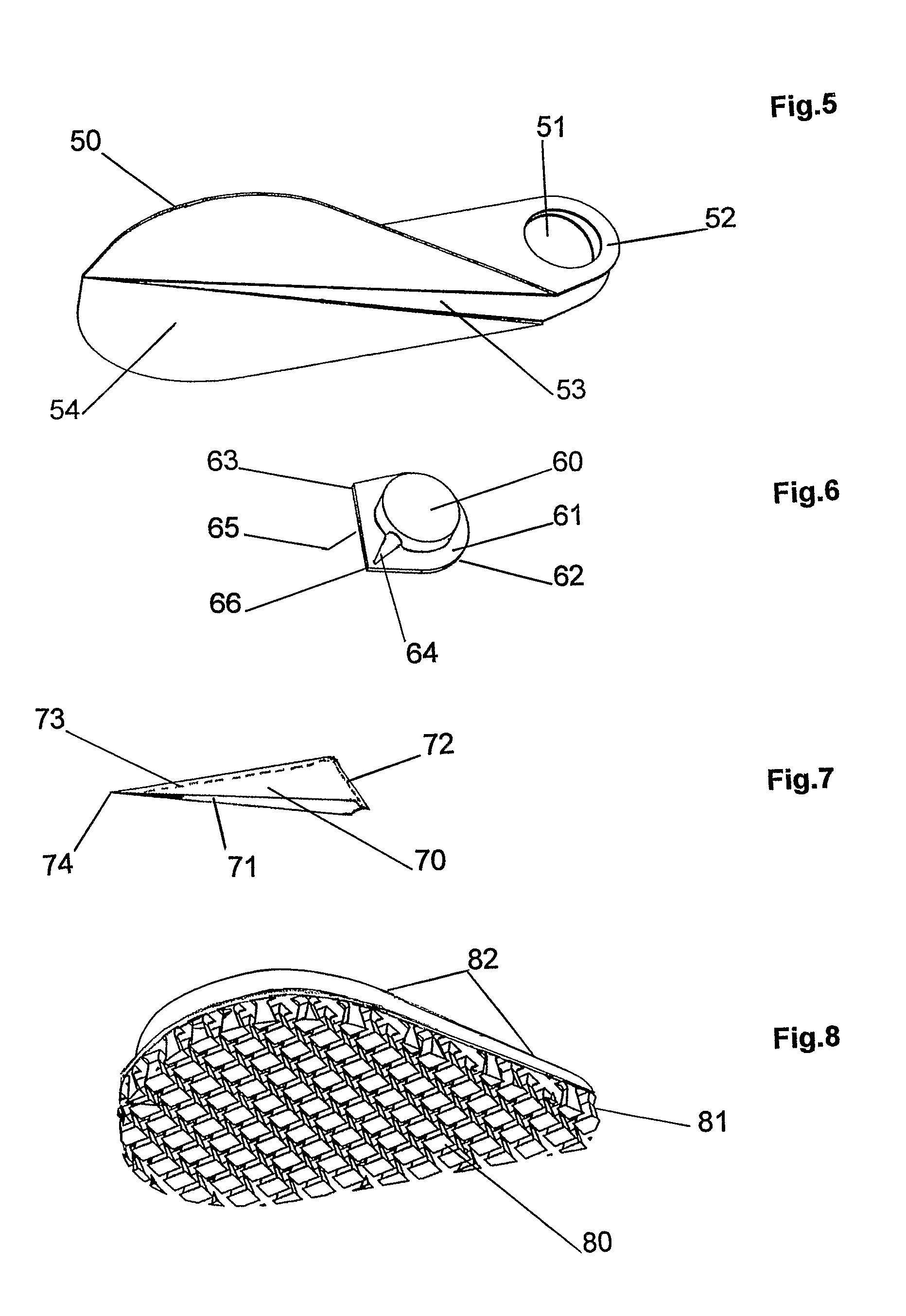
[0114]Referring to FIG. 5, a Tool with a fin (50) and first face (54) is similar to Tool shown in FIG. 3 but with an enlarged hole (51) surrounded by a thin retaining ring (52) and the folded spined portion is shown opened slightly (53) and this may be sprung open further to allow the capsule shown in FIG. 6 to be inserted into hole (51).

[0115]FIG. 6 shows the capsule that c...

example 3

Techniques for Handling and Using the Small Tool

[0120]The small Tools are hand held and typically range up to 100 mm from distal to proximal end. Average human index and second fingers range from 60 to 90 mm long, thus the small Tools are sized to be held by these fingers and in some cases fingers and the thumb. Generally small tools find most use in skin care, cosmetics, first aid and artistic applications.

[0121]FIG. 9 shows a small Tool gripped on spined-portion (90) for rubbing, held towards proximal end (91) between thumb (92) and index finger (93) and second finger (94). During rubbing the Tool is placed in frictional contact with a surface and rubbed in some combination of the direction arrows (95, 96) (97). Also shown in FIG. 9 is a swab pad (98) mounted above the fin (99).

[0122]FIG. 10 shows the Tool inverted for wiping and scraping, held between the same fingers as above. The wiping face (100) (Tool second face) is moved in the direction of arrows (101) to scrape residues i...

example 4

Construction of Medium Size Tools

[0125]Medium size Tools are scaled up versions of the small Tools, the distance between their distal and proximal ends being within the range of 100 mm to 200 mm on spined-portion. Generally these sized tools are useful for domestic cleaning.

[0126]FIG. 13 shows a medium size Tool with spined-portion (130) approximately 150 mm long pivotally coupled with a coupling (131) pivoting at point (135) on a button pump body (132) carrying a button (133), the pump body (132) joined to a 300 ml storage bottle (134), the outside of the storage bottle used as a handle, with which to hold the Tool. The coupling (131) has two pivot points, the first (135) pivots on the pump body (132) and the second (136) pivots on the spined-portion (130). Stuff is dispensed via tube (137) shown located at Tool distal end. When using the Tool and holding the storage bottle (134) the index finger is pressed against pad (138) to control the pivoting rubbing face (139) and hold it ag...


PUM


Abstract

A tool for treating a surface by rubbing and including means to dispense onto the surface stuff, for example, a lotion for skin treatment, and including also a pair of opposed fins which are supported by a stiff, tapered, upstanding spine portion that traverses the tool and has an upper radial face for wiping and scrapping stuff, the fins extending laterally of and along the lower length of the spine portion and having an under face for rubbing contact with the surface, and each fin having optionally an upper absorbent face on each side of the spine portion to provide a swabbing capability, and the tool having a distal end and a proximal end, with the upstanding spine portion narrowing toward the distal end of the tool and the spine portion being hollow and shaped towards the proximal end for holding of the tool directly or coupled to a holdable object and also a method for making the tool.

Description

CROSS-REFERENCE TO RELATED APPLICATIONS[0001]This application is the National Phase entry of PCT / GB2005 / 002014, filed May 20, 2005, which claims priority to British patent application number 0411467.4, filed May 22, 2004 and British application number 0503904.5, filed Feb. 25, 2005.FIELD OF THE INVENTION[0002]The present inventions relates to chemical-mechanical surface treatment Tools for treating and cleaning surfaces, the Tools dispense and collect up stuff and are made with layered materials.BACKGROUND[0003]This invention addresses problems associated with treating and cleaning surfaces as encountered in many areas of human activity like domestic and institutional cleaning, cleaning automobiles, personal care, first aid and manufacturing. The problem is the inconvenience caused by the number of actions and items required to treat and clean a surface, the effort involved and risks associated with repeated exposure of hands to chemicals.[0004]What is needed is a Tool shaped to per...

Claims


Application Information

Patent Timeline
Patent Type & Authority Patents(United States)
IPC IPC(8): B43K5/00B05C11/00A45D34/04A47L13/22A47L13/26A61M35/00B65D83/14
CPCA45D34/04A45D2200/1018A45D2200/1054A45D2200/1063A45D2200/207A47L13/26A47L13/10A47L13/12A47L13/28B05C1/00
Inventor LINZELL, GEOFFREY ROBERT
Owner LINZELL GEOFFREY ROBERT
Learn More