Stator arrangement, generator and wind turbine

a generator and wind turbine technology, applied in the direction of electric generator control, magnetic circuit shape/form/construction, magnetic circuit rotating parts, etc., can solve the problems of comparatively rigid stator segments, and large and heavy generators, so as to achieve the lack of stiffness to maintain cylindricity

Active Publication Date: 2012-09-25
SIEMENS GAMESA RENEWABLE ENERGY AS
View PDF10 Cites 17 Cited by
  • Summary
  • Abstract
  • Description
  • Claims
  • Application Information

AI Technical Summary

Benefits of technology

[0008]It is advantageous when the generator stator comprises a series of independent stator segments. When manufacturing the stator the active elements are much easier to handle if manufactured as segments, and a segmented stator has the benefit that in case of a fault the respective affected stator segment can be replaced at a fraction of the costs and effort as would be required for the replacement of the complete stator.
[0011]It is therefore an object of the present invention to provide a segmented stator arrangement, a generator as well as a wind turbine as initially mentioned in such a way, that the air gap distance can be very precise in respect of form and dimension tolerances, especially cylindricity, roundness and diameter without needs for excessive support structures.
[0017]The stator arrangement is particularly advantageous because the stator support structure can be made very stiff without any consequence for the external dimensions of the generator. The stator support structure can have a very large sectional height, basically comprising all of the space between the generator shaft and the inner surface of the stator segment laminate stack. This means that it is easy to provide such stiffness as is required to ensure the necessary support for the segments so that the air gap—also during operation of the generator—can be maintained precisely in the desired range of radial distance between the inner stator and the outer rotor.
[0018]Due to the fact that stiffness increases with the square of the section height, the supporting structure can easily be made an order of magnitude stiffer than for an outer stator.
[0024]In an alternative embodiment the stator support structure comprises two end plates that are mounted each via bearings to a radial outer surface of the shaft, whereas the shaft is pivotable. This allows having the stator fixed in relation to the casing of the generator even though the shaft and the surface of the shaft adjacent to the inner circumference of the end plates rotate around its axis. Together with the height of the bearings the end plates guarantee a precise distance of the stator laminate stacks to the shaft or to the axis of the generator. This again then guarantees the width of the air gap because the outer rotor is connected and rotatably coupled to the same rotating shaft.

Problems solved by technology

Maintaining the air gap in the range of a few millimeters between the rotor elements and the stator elements of a generator of such dimensions requires a comparatively rigid and therefore massive and heavy support structure, in particular of the stator arrangement.
With traditional inner rotor machines have the stator support structure on the outside, consequently this lead to large and heavy generators.
The segmentation of a stator on the other hand has a drawback in the lack of stiffness to maintain cylindricity.
For a segmented generator, the laminate stacks do not provide any stiffness that assists to maintain cylindricity of the stator.

Method used


Image

  • Stator arrangement, generator and wind turbine
  • Stator arrangement, generator and wind turbine
  • Stator arrangement, generator and wind turbine

Examples


Embodiment Construction

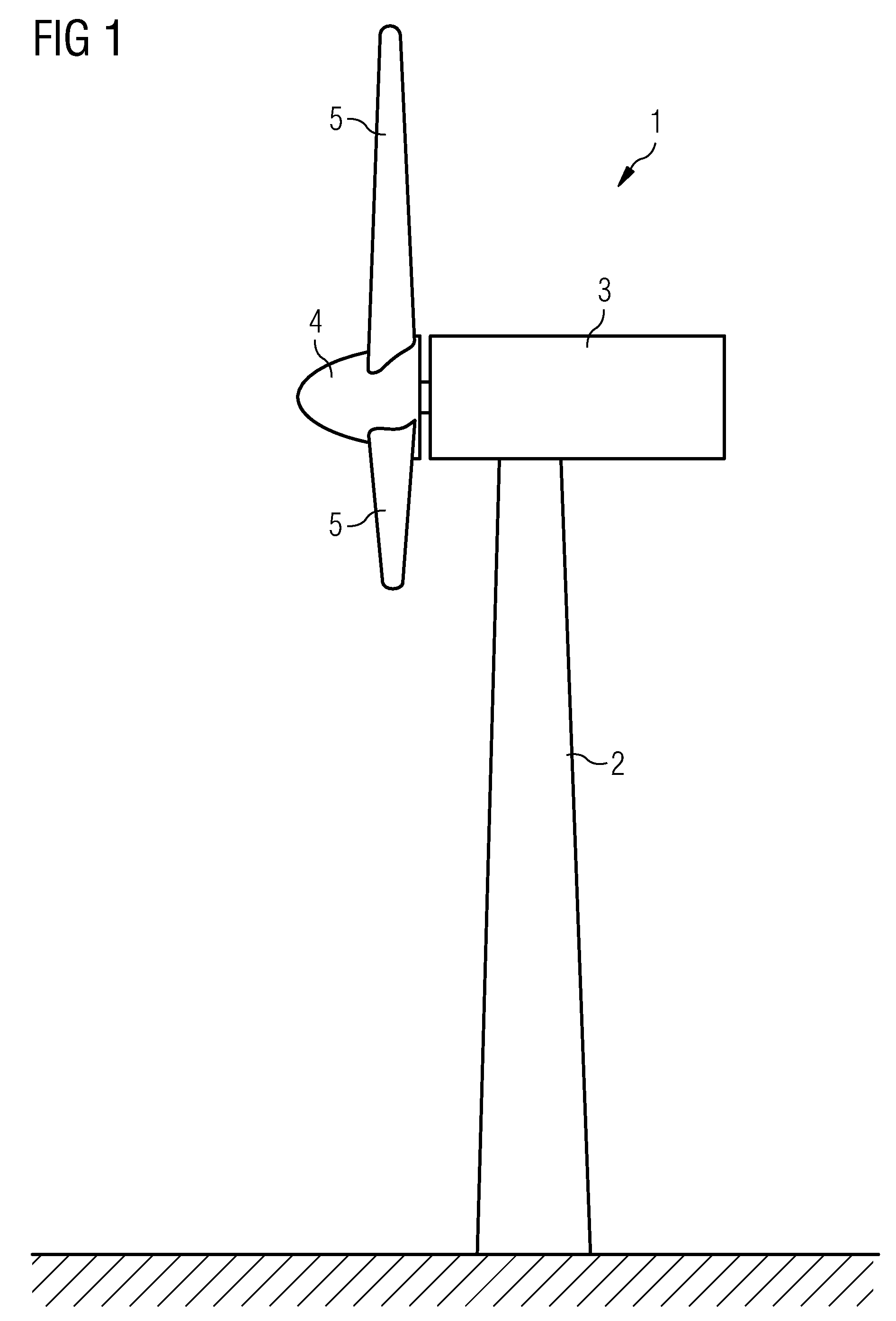
[0031]FIG. 1 shows a wind turbine 1 comprising a tower 2, a nacelle 3 and a hub 4 with rotor blades 5. In the nacelle 3 several further components of the wind turbine 1 are arranged like a generator 11 as it is schematically shown in FIG. 2. The generator 11 is in a not shown manner connected to the hub 4 for the production of electrical energy and has a substantially horizontally aligned centre axis A.

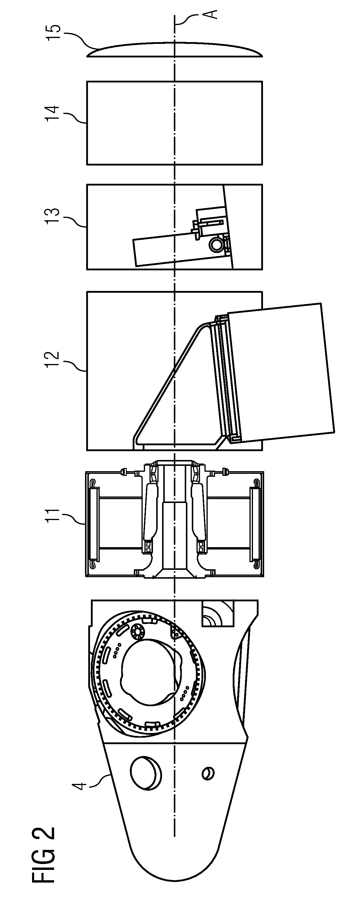
[0032]FIG. 2 shows some basic components of a wind turbine 1. The components are shown with a slight gap between each other, even though when assembled, these gaps are closed. Again, a hub 4 is shown to which the rotor blades—not shown—will be attached. Further components, each adjacent to each other, are the generator 11, the load / bearing section 12, which has a connection to the not shown tower 2. Next, further components are a control unit 13, cooling equipment 14, and an end cap 15.

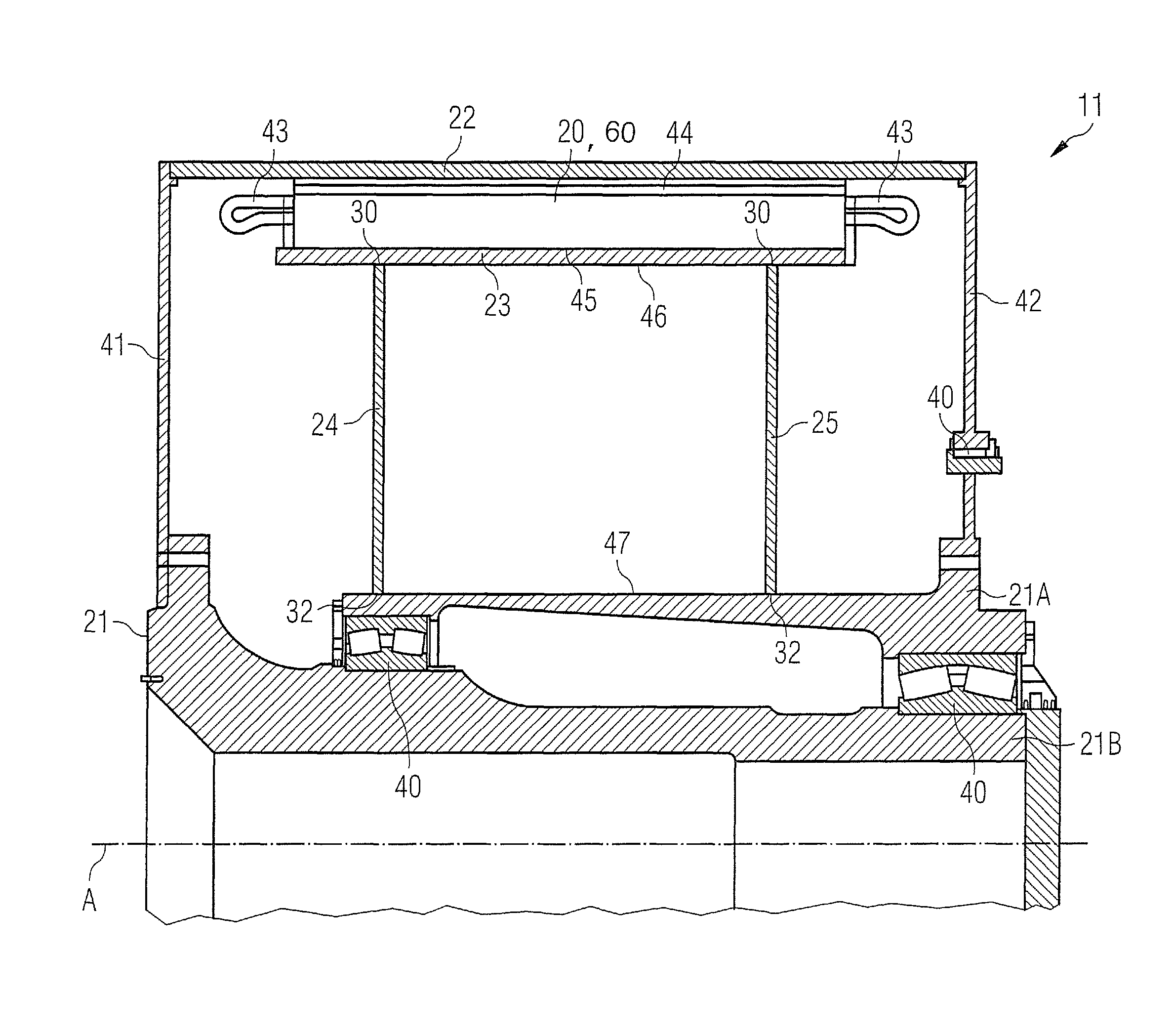
[0033]FIG. 3 shows one embodiment of the generator 11 as the inventive electric machine with the inv...


PUM


Abstract

A stator arrangement of an electric machine, generator, and wind turbine includes a plurality of stator segments forming substantially the stator of the electric machine in a cylindric form around a radially centered shaft. The stator arrangement is radially surrounded by a rotatably mounted rotor arrangement. The stator segments are radially mounted on an outer surface of a support structure. The support structure is fixed via rigid connections to the shaft.

Description

CROSS REFERENCE TO RELATED APPLICATIONS[0001]This application claims priority of European Patent Office application No. 08016228.2 EP filed Sep. 15, 2008, which is incorporated by reference herein in its entirety.FIELD OF INVENTION[0002]The invention relates to a stator arrangement of an electric machine, especially of a generator for a wind turbine. The invention concerns also a generator, e.g. a direct drive generator for a wind turbine comprising such a stator arrangement as well as a wind turbine comprising such a generator.BACKGROUND OF INVENTION[0003]Each wind turbine comprises a generator, e.g. a large direct drive generator having a generator stator and a generator rotor for the production of electrical energy.[0004]In order to achieve a relatively high efficiency of a generator, in particular of a generator of a wind turbine, a radial air gap between the rotor elements, e.g. permanent magnets, and the stator elements, e.g. a laminate stack with windings, of the generator sh...

Claims


Application Information

Patent Timeline
Patent Type & Authority Patents(United States)
IPC IPC(8): H02K1/18F03D9/00
CPCF03D9/002H02K1/148H02K5/1737H02K7/1838H02K21/22F05B2220/7066H02K2213/12Y02E10/721Y02E10/725F03D9/25Y02E10/72
Inventor STIESDAL, HENRIK
Owner SIEMENS GAMESA RENEWABLE ENERGY AS
Why Eureka
Try Eureka