Initialization of a data processing system

a data processing system and initialization technology, applied in the direction of program control, multi-programming arrangement, instruments, etc., can solve the problems of time-consuming control of these chips, large computer systems, and possible redundant service control networks

Active Publication Date: 2012-09-25
INT BUSINESS MASCH CORP
View PDF9 Cites 4 Cited by
  • Summary
  • Abstract
  • Description
  • Claims
  • Application Information

AI Technical Summary

Benefits of technology

[0016]The automatic parallelization approach of the present invention allows for the increase in the utilization of the system management controller. Delays in the initialization phase of the data processing system that are caused by dependencies between initialization steps for functional hardware element can be minimized.
[0017]In some embodiments of the present invention, knowledge about the dependencies between initialization steps is stored and maintained in a single place, the control flow table. This allows for easy and quick modification of the sequence of initialization steps for the functional hardware elements. This is may be helpful for late hardware design changes and hardware and firmware problems that are detected late in the design cycle. In reality, hardware designers often introduce changes late in the development that need to be reflected in the initialization sequence or even lead to additional dependencies between functional hardware elements. For example, it can be realized late that too much power would be consumed when performing many initialization steps of the same type at once (e.g., chip self-tests).

Problems solved by technology

The exponential growth of computing requirements has resulted in the creation of large complex computer systems.
In addition, the service control network may be redundant.
However, there are dependencies between the operations of the cage controllers that must be reflected in the operation of the system control tasks performed on the support element.
These dependencies are caused by the fact that hardware in the various cages does not work independently from each other.
With the growing number of chips in complex computer systems (e.g., systems with Multi-Chip Modules), especially in high-end server computer systems, the task of controlling these chips can become time intensive.
The problem may worsen for hardware designs that do not support broadcasting of operations to multiple chips at once.
In system control structures similar to the IBM eServer z900, the cage controllers alone may provide limited parallelization options only.
But this does not fully exploit the capabilities to parallelize operations as both initializations can overlap to some extent (at some point a CPU will access its associated memory chips, but needs to be configured accordingly in order to do so, e.g. via certain register settings).

Method used


Image

  • Initialization of a data processing system
  • Initialization of a data processing system
  • Initialization of a data processing system

Examples


Embodiment Construction

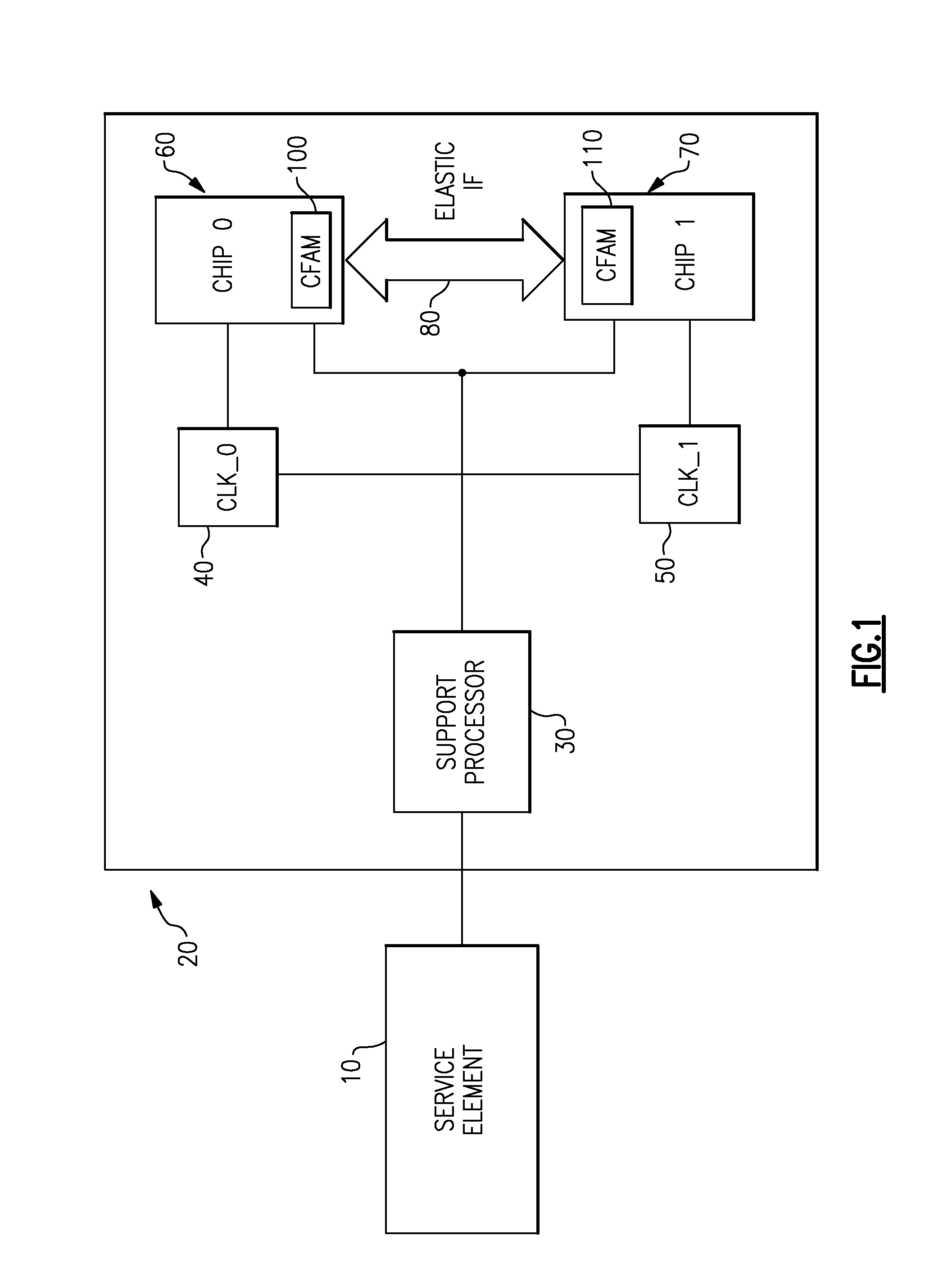
[0025]FIG. 1 illustrates a system control structure for a subsystem of a computer system used for an embodiment of the present invention. A service element 10 controls a node 20 of the computer system. For example, the node 20 could be a rack-mountable cage for an industry standard (EIA 310-D, IEC 60297 and DIN 41494 SC48D) 19-inch rack. The node 20 houses a support processor 30, which is responsible for the system management of the node 20. The support processor 30 is connected to the service element 10, e.g. via a private system control service network based on Ethernet technology. An example of service element 10 is a personal computer, e.g., an IBM ThinkPad. The service processor 30 can be implemented as an ASIC (Application Specific Integrated Circuit), e.g., the IBM eServer z900 cage controller ASIC (e.g., FIG. 7 in Batinger et al. cited above). A detailed implementation description for such an ASIC is given in J. Saalmueller / J. Wuertz “Embedded Controllers for solving complex...


PUM


Abstract

Technique for initializing a data processing system. Sequences of initialization steps for selected functional hardware elements of a data processing system are defined and dependencies between the initialization steps are determined. These definition steps are preferably performed during the design and development of the data processing system. The sequences of initialization steps and their dependencies are represented in a single control flow table. This control flow table is then analyzed by a system management controller during an initialization phase of the data processing system. The sequences are associated with selected functional hardware elements and for each associated sequence of initialization steps the system management controller generates and executes a parallel thread of execution.

Description

BACKGROUND OF THE INVENTION[0001]The present invention relates to the power-on initialization steps in data processing systems, particularly in computer systems.[0002]The exponential growth of computing requirements has resulted in the creation of large complex computer systems. Power-on and initialization of these large computer systems up to the point at which normal operating systems are fully available often rely on embedded controllers that facilitate the initialization of a computer system at power-on. An example for such a complex control structure of a computer system is described in F. Baitinger et al “System control structure of the IBM eServer z900”, IBM J. Res. & Dev., Vol. 46, No. 4 / 5, 2002, pp. 523-535.[0003]In such a computer system, the hardware is packaged in multiple hardware “cage enclosures”, the so-called cages. The embedded controllers are divided in two categories: support elements and cage controllers. The support elements are optionally redundant with a prim...

Claims


Application Information

Patent Timeline
Patent Type & Authority Patents(United States)
IPC IPC(8): G06F15/177G06F9/46
CPCG06F9/445G06F9/46G06F9/4401
Inventor NICKLAUS, WALTERSCHAUFLER, RALFSCHULZE, JOERG
Owner INT BUSINESS MASCH CORP
Why Eureka
Try Eureka