
Control device for a rail vehicle

a control device and rail vehicle technology, applied in the direction of climate sustainability, braking system, locomotive, etc., can solve the problems of increasing the complexity of technical equipment, affecting reliability, and affecting reliability, so as to reduce equipment expenditure, improve diagnostic efficiency, and shorten downtime

Active Publication Date: 2012-10-02
KNORR BREMSE SYST FUR SCHIENENFAHRZEUGE GMBH
View PDF32 Cites 1 Cited by
  • Summary
  • Abstract
  • Description
  • Claims
  • Application Information

AI Technical Summary

Benefits of technology

The present control device is a combined brake control device and anti-skid device for a rail vehicle. The device includes an electronic rolling gear monitoring control unit that senses the rotational speed of the wheels and a roll monitoring device that senses disturbances in the rotation of the wheels. The device also includes an electronic anti-skid control unit that controls the brakes and monitors the wheel slip. The use of a single structural unit composed of these control units reduces complexity and costs. The device can also use common components and interfaces for communication, reducing expenditure on equipment. The use of the rolling gear monitoring device allows for early detection of damaged components, reducing downtimes and costs.

Problems solved by technology

The problem with these running gear monitoring devices as systems with separate structures (stand-alone solution) is the relatively high complexity of and costs for their implementation.
This is because installing such a system requires additional assemblage, sensors, cabling and installation space.
Furthermore, the complexity of the technical equipment is increased, which has adverse effects on reliability.

Method used


Image

  • Control device for a rail vehicle
  • Control device for a rail vehicle
  • Control device for a rail vehicle

Examples


Embodiment Construction

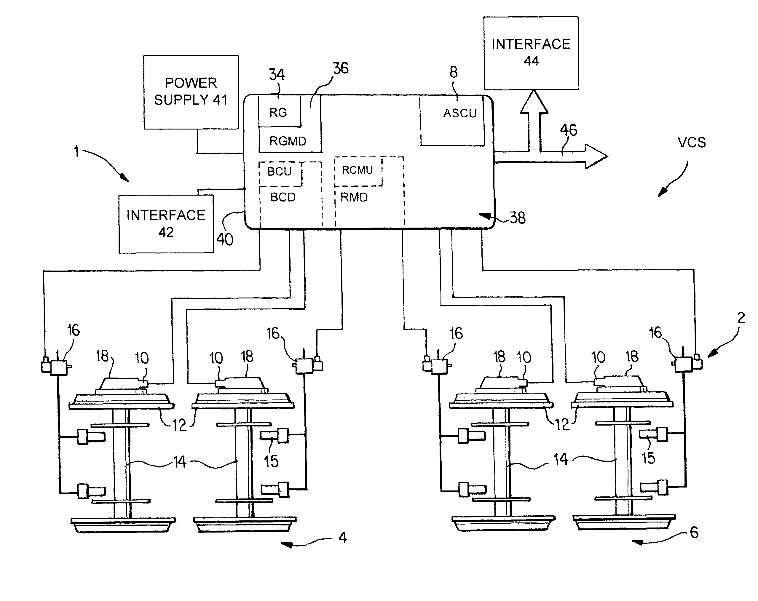
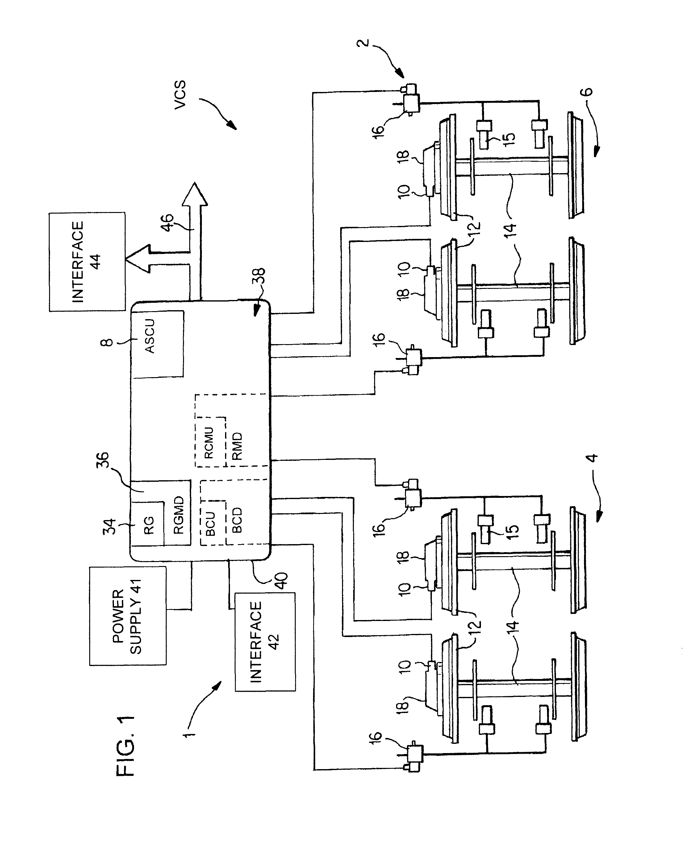
[0023]FIG. 1 is a schematic illustration of the design of an anti-skid device 1 of a rail car 2 with two dual-axle bogeys 4, 6. The rail car 2 is configured, for example, for a speed up to 200 km / h.

[0024]The anti-skid device 1 has an electronic anti-skid control unit 8 and sensors 10 on, for example, each wheel 12 of an axle 14 of a bogey 4, 6. The sensors 10 detect the instantaneous rotational speed of the respective axle or of the respective wheel. However, in FIG. 1, such a sensor 10 is illustrated on only one side of the axle in each case, for reasons of clarity. A microprocessor of the electronic anti-skid control unit 8 calculates the actual vehicle speed or train speed in a known fashion and reduces the brake cylinder pressure, predefined by the brake control device arranged in a driver's vehicle (not illustrated), in a brake cylinder 15 by electropneumatic anti-skid valves 16 on an axle by axle basis. The axles 14 are secured in a rotatable fashion by, in each case, two whee...


PUM


Abstract

A control unit for a rail vehicle, comprising a braking control unit that contains an electronic braking control device for emitting control commands to brake actuators and / or comprising an anti-skid device, which controls the wheel slip of the wheels of at least one axle in accordance with at least one rotational speed signal from an anti-skid sensor. The control unit also comprises a roll monitoring unit with an electronic roll monitoring control device and at least one roll monitoring sensor for detecting the rotational speed of at least some wheels in the form of a rotational speed signal, and comprises a rolling gear monitoring unit for monitoring and / or diagnosing critical conditions of and damage to the rolling gear. The monitoring unit comprises an electronic control device for monitoring the rolling gear. The electronic control device for monitoring the rolling gear and / or the electronic anti-skid control device and / or the electronic braking control device and / or the electronic roll monitoring control device are combined to form a structural unit.

Description

BACKGROUND AND SUMMARY OF THE INVENTION[0001]The present control device is for a rail vehicle having a brake control device and / or an electronic roll monitoring control unit and with a rolling gear monitoring device. The brake control device includes an electronic brake control unit for outputting control commands to the brake actuators. The anti-skid device controls the wheel slip of the wheels of at least one axle as a function of at least one rotational speed signal supplied to an electronic anti-skid control unit by an anti-skid sensor. The roll monitoring device includes an electronic roll monitoring control unit and at least one roll monitoring sensor for sensing the rotational speed of at least a number of wheels in the form of a rotational speed signal. The rolling gear monitoring device monitors and / or for diagnoses the rolling gear with respect to critical states and damage such as, for example, derailment, overheated bearings, unstable running and the like, and includes a...

Claims


Application Information

Patent Timeline
Patent Type & Authority Patents(United States)
IPC IPC(8): B60T13/00B60T15/14B60T8/88
CPCB60T8/321B60T8/3235B61K9/00B61C15/14B60T17/228Y02T30/00B60T17/22B60T8/32
Inventor AURICH, STEFANSCHUHMACHER, JOHANNESWACH, JORG-JOHANNESFRIESEN, ULF
Owner KNORR BREMSE SYST FUR SCHIENENFAHRZEUGE GMBH
Learn More