

End mill
a technology of end mills and end plates, which is applied in the direction of metal-working equipment, metal-working apparatus, milling equipment, etc., can solve the problems of reducing the thickness affecting the smooth discharging of chips, and losing the good rigidity of the top portion of the end mill body. , to achieve the effect of improving the rigidity, preventing stress concentration, and good chip discharge performan
- Summary
- Abstract
- Description
- Claims
- Application Information
AI Technical Summary
Benefits of technology
Problems solved by technology
Method used
Image

Examples
Embodiment Construction
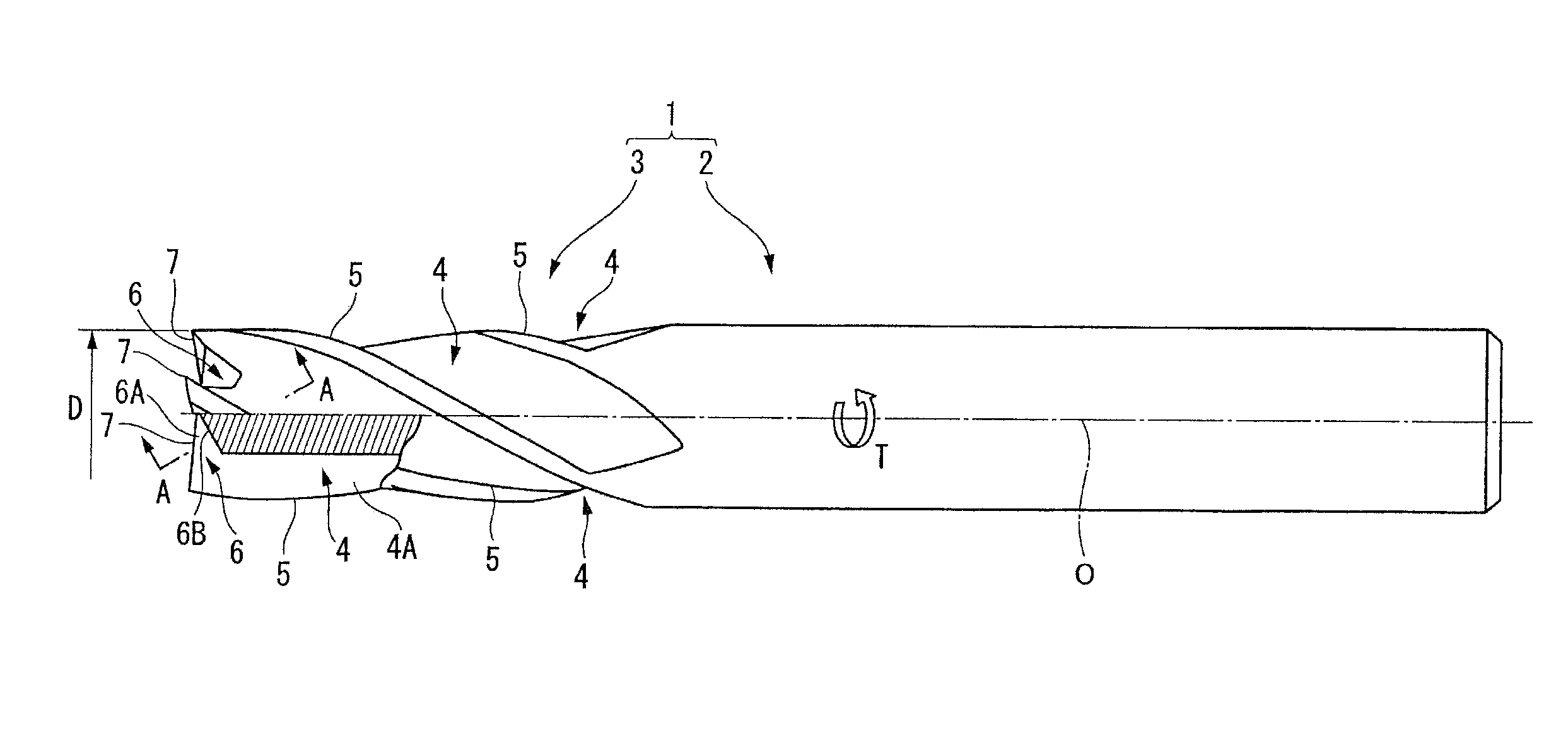
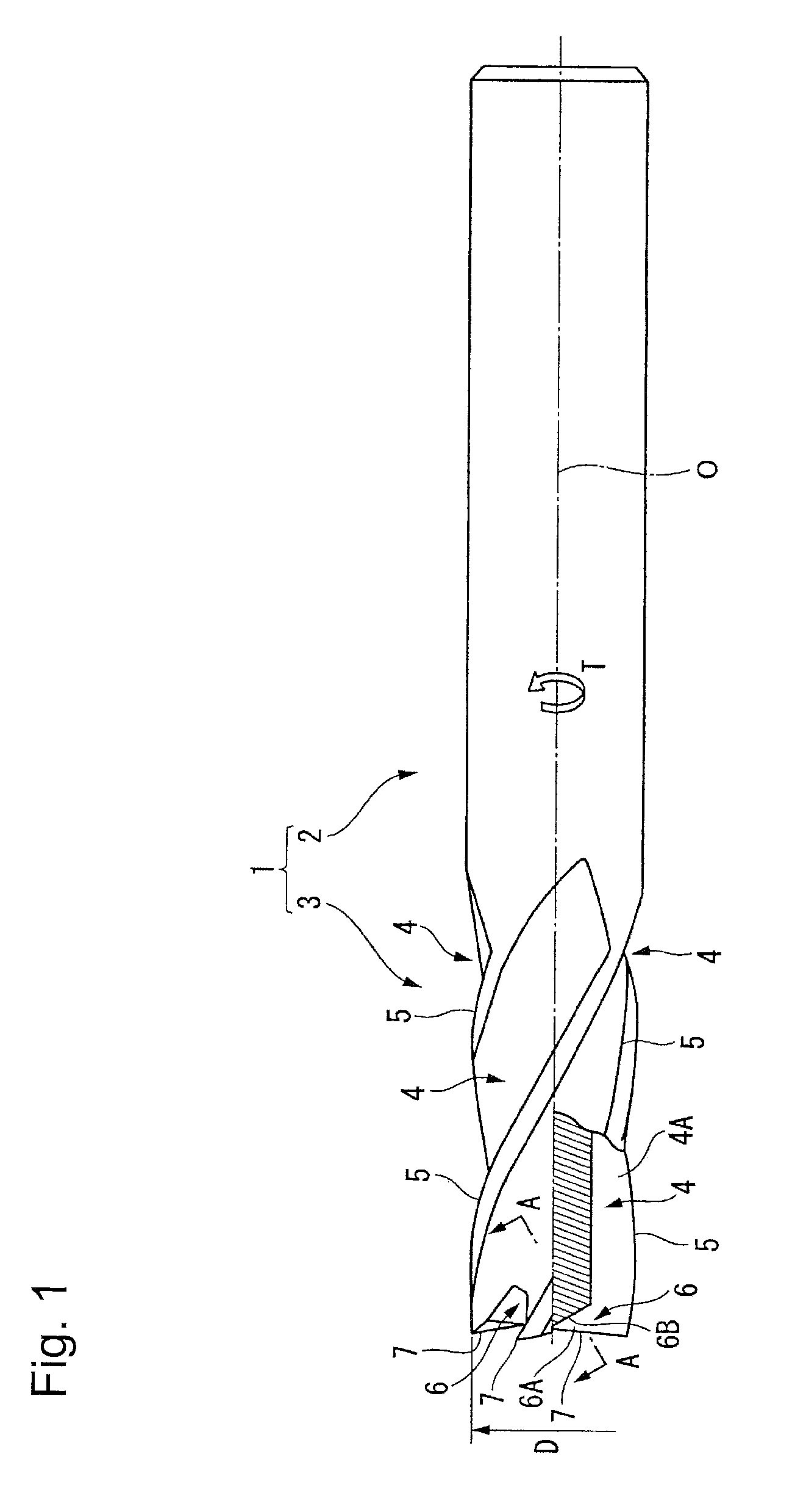
[0040]In a first preferred embodiment of the invention shown in FIGS. 1 and 2, an end mill body 1 is made of a hard material such as cemented carbide, and has a substantially cylindrical shape having an axis O is its center axis. A rear end part (a right part in FIG. 1) of the end mill body is a shank part 2 having a cylindrical shape, and a top part (a left part in FIG. 1) of the end mill body is a cutting edge part 3. As the first step in using an end mill according to the present invention, the shank part 2 is fixed to a spindle of a machine tool and rotated in an end mill rotating direction T on the axis O. The end mill is then fed in a direction intersecting the axis O, enabling the cutting edge part 3 to cut into a workpiece to machine it.
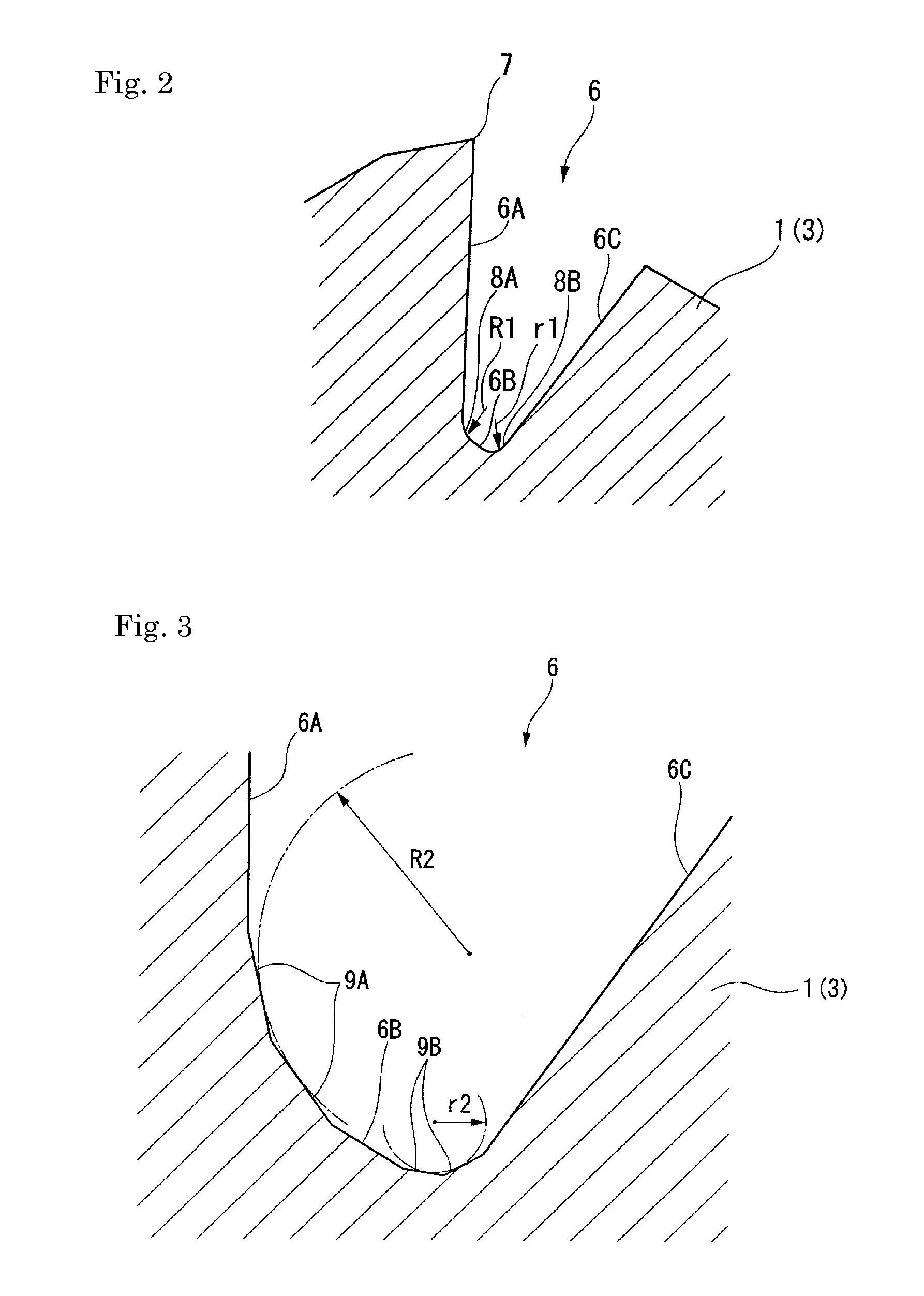
[0041]Three or more flutes 4 (four in this illustrated embodiment of FIGS. 1 and 2) in a helix shape in a reverse direction to the end mill rotating direction T around the axis O from the top side toward the rear end side, are formed in the p...
PUM
 Abstract
Description
Claims
Application Information