
Method for measuring thickness

a technology of thickness measurement and thickness, applied in the direction of measuring devices, instruments, using optical means, etc., can solve the problems of interference signals that cannot be used to a transparent subjecting layer b, and the thickness of the subjecting layer b>20/b> cannot be obtained, so as to achieve accurate measurement and reduce the process and time required for measuring thickness

Active Publication Date: 2012-10-02
SNU PRECISION CO LTD
View PDF11 Cites 3 Cited by
  • Summary
  • Abstract
  • Description
  • Claims
  • Application Information

AI Technical Summary

Benefits of technology

[0018]According to the present invention, in a method for measuring a thickness, a difference between the phase of an interference signal generated at a boundary surface between an air layer and a base layer and the phase of an interference signal generated at a boundary surface between a thin layer and a base layer is measured so that thickness below micrometer of a transparent thin layer is accurately measured.
[0019]Also, when a correlation equation between a thickness and a phase difference is obtained by using sample layers, which have the same material as a transparent thin layer to be measured and have thicknesses different from each other, it is possible to measure the thickness of a thin layer only by obtaining a phase different between a boundary surface between a transparent thin layer to be measured and a base layer and a boundary surface between an air layer and a base layer. Therefore, processes and time required for measuring the thickness can be reduced.

Problems solved by technology

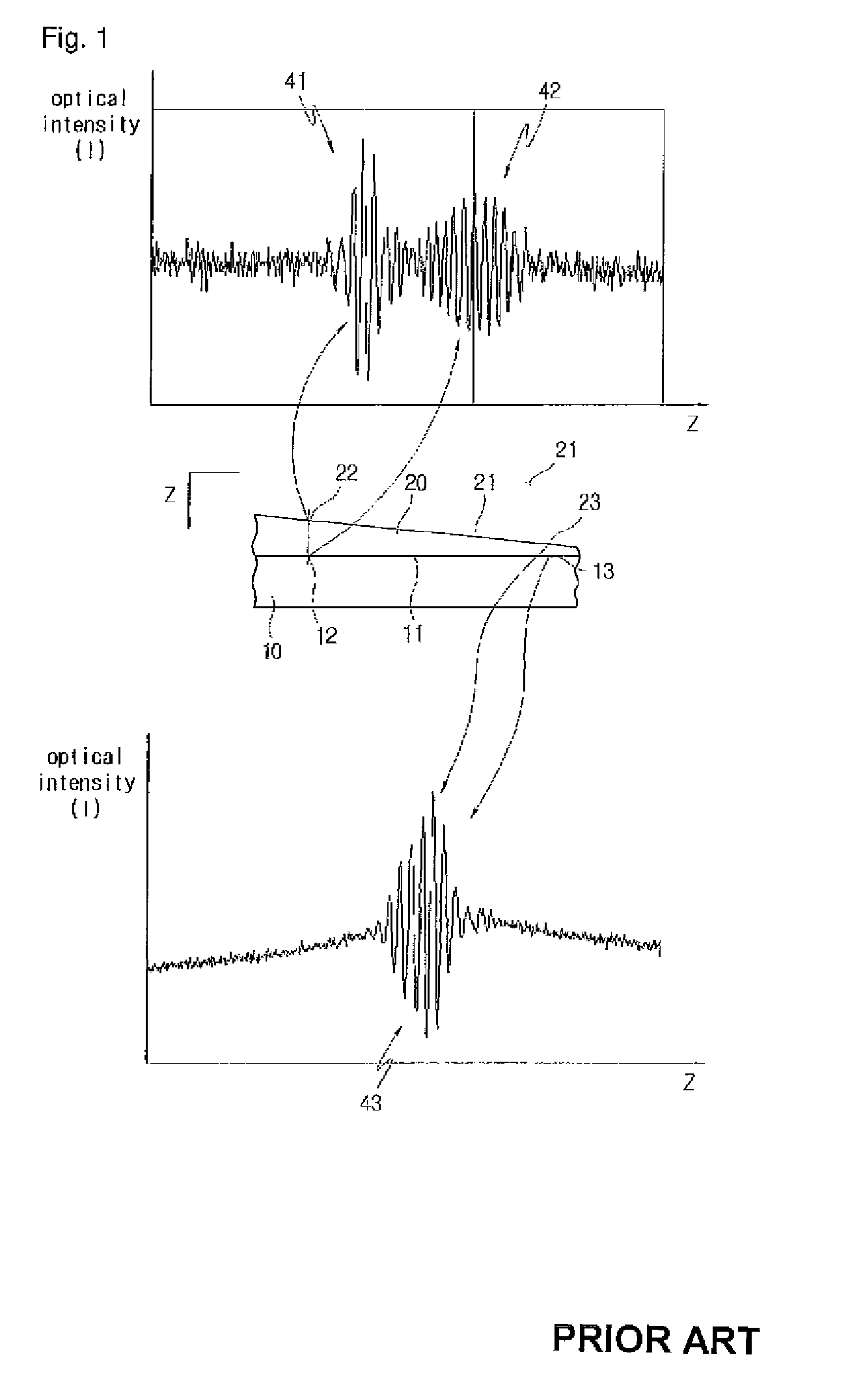
However, at a position 23 where the subjecting layer 20 has a relatively thin thickness, it is impossible for the thickness of the subjecting layer 20 to be obtained through the above described method.
Therefore, there is a problem in that interference signals can not be used to a transparent subjecting layer 20 having a thin thickness.

Method used


Image

  • Method for measuring thickness
  • Method for measuring thickness
  • Method for measuring thickness

Examples


Embodiment Construction

[0029]Hereinafter, embodiments of a method for measuring a thickness according to the present invention will be described in detail with reference to the following drawings.

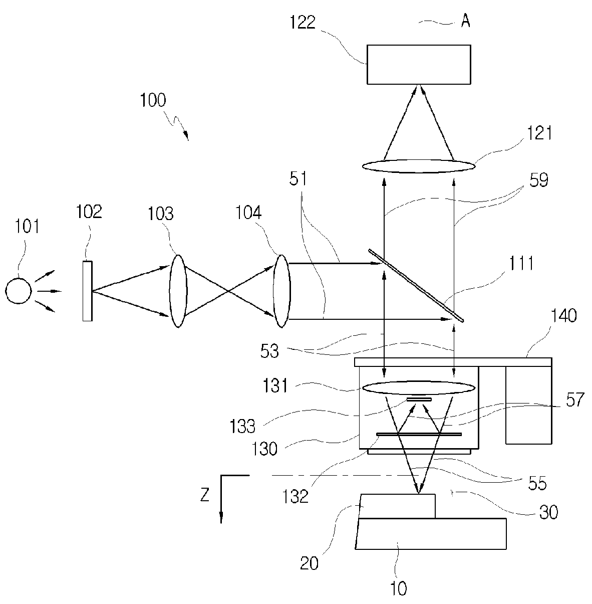
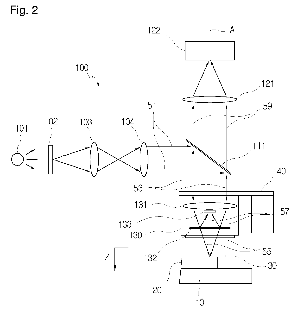
[0030]FIG. 2 is a view illustrating an interferometer used for implementing a method for measuring a thickness according to the present invention.

[0031]With reference to FIG. 2, the interferometer 100 employs the structure of a mirau interferometer which is typically used for measuring a thickness of a transparent thin layer. The interferometer 100 includes a white optical source 101. A lamp having various kinds of sources, such as a halogen lamp, may be used as the white optical source 101. In order to reduce only brightness of incident light from the white optical source 101 while maintaining the characteristic of a spectrum thereof, an ND filter (Neutral Density filter) is used. The interferometer 100 includes a condenser lens 103 for condensing light passed through the ND filter 102. Light passed through the ...


PUM


Abstract

Disclosed is a method for measuring a thickness of a subjecting layer attached on a base layer by means of an interferometer, which includes the steps of: obtaining a correlation equation of a phase difference with respect to thicknesses of sample layers, the thicknesses being different from each other, the sample layers being made from a material substantially equal to a material of the subjecting layer; obtaining a first interference signal with respect to an optical axial direction incident to the base layer at a boundary surface between an air layer and the base layer; obtaining a second interference signal with respect to the optical axial direction at a boundary surface between the subjecting layer and the base layer; obtaining a phase difference between a phase of the first interference signal and a phase of the second interference signal at respective heights substantially equal to each other with respect to the optical axial direction; and determining a thickness of the subjecting layer by inserting the phase difference into the correlation equation.

Description

CROSS REFERENCE TO RELATED APPLICATION[0001]This application is the national stage entry of International Patent Application No. PCT / KR2008 / 001833 having a filing date of Apr. 1, 2008, which claims filing benefit of Korean Patent Application Number 10-2008-0010300 having a filing date of Jan. 31, 2008.TECHNICAL FIELD[0002]The present invention relates to a method for measuring a thickness, and more particularly to a method for measuring phase change of interference light with respect to a boundary surface between a transparent thin layer and a base layer so as to accurately measure thickness of the transparent thin layer having a thickness below micrometer.BACKGROUND ART[0003]Among various factors influencing quality of a semiconductor or a FPD in a semiconductor process and a FPD process, it is an important factor to control the thickness of a thin layer, so that it is necessary to directly monitor the thickness of the thin layer during the processes. ‘A thin layer’ is a base layer...

Claims


Application Information

Patent Timeline
Patent Type & Authority Patents(United States)
IPC IPC(8): G01B11/02
CPCG01B11/0675G01B11/06G01B9/02
Inventor PAHK, HEUI-JAEHWANG, YOUNG-MINAHN, WOO-JUNG
Owner SNU PRECISION CO LTD
Learn More