Inertial barrier

a technology of inner walls and outer walls, applied in roadway safety arrangements, roads, construction, etc., can solve the problems of requiring the maintenance of the outer walls or the outer walls, and the orientation of the outer walls to be reversed, so as to achieve the effect of adding strength and rigidity

Active Publication Date: 2012-10-09
PLASTIC SAFETY SYST
View PDF22 Cites 2 Cited by
  • Summary
  • Abstract
  • Description
  • Claims
  • Application Information

AI Technical Summary

Benefits of technology

[0006]In accordance with one aspect of the invention, the container has a bottom wall and open top and a side wall having a ledge extending laterally inwardly therefrom in spaced relation from the bottom wall and open top for supporting an insert thereon used to support a suitable dispersible granular energy absorbing material such as sand above the insert inside the container. The insert has an axially upwardly, radially inwardly extending top wall and is made of a suitable plastic material that permits some downward flexing of the insert inside the container as the weight of the material that is placed on top of the insert builds up, causing the insert to expand and push radially outwardly against the side wall, preventing the material from leaking past the insert.
[0008]In accordance with another aspect of the invention, the container side wall may have a plurality of circumferentially spaced axially extending ribs to give added strength and rigidity to the side wall.

Problems solved by technology

However, this has the disadvantage that an inventory of the different sizes of pedestals or cores must be maintained in order to construct barrier units of the desired weight configurations.
However, this has the disadvantage that because of the shape of the core, the orientation of the core must be reversed for achieving all of the desired barrier weight configurations.

Method used


Image

  • Inertial barrier
  • Inertial barrier
  • Inertial barrier

Examples


Embodiment Construction

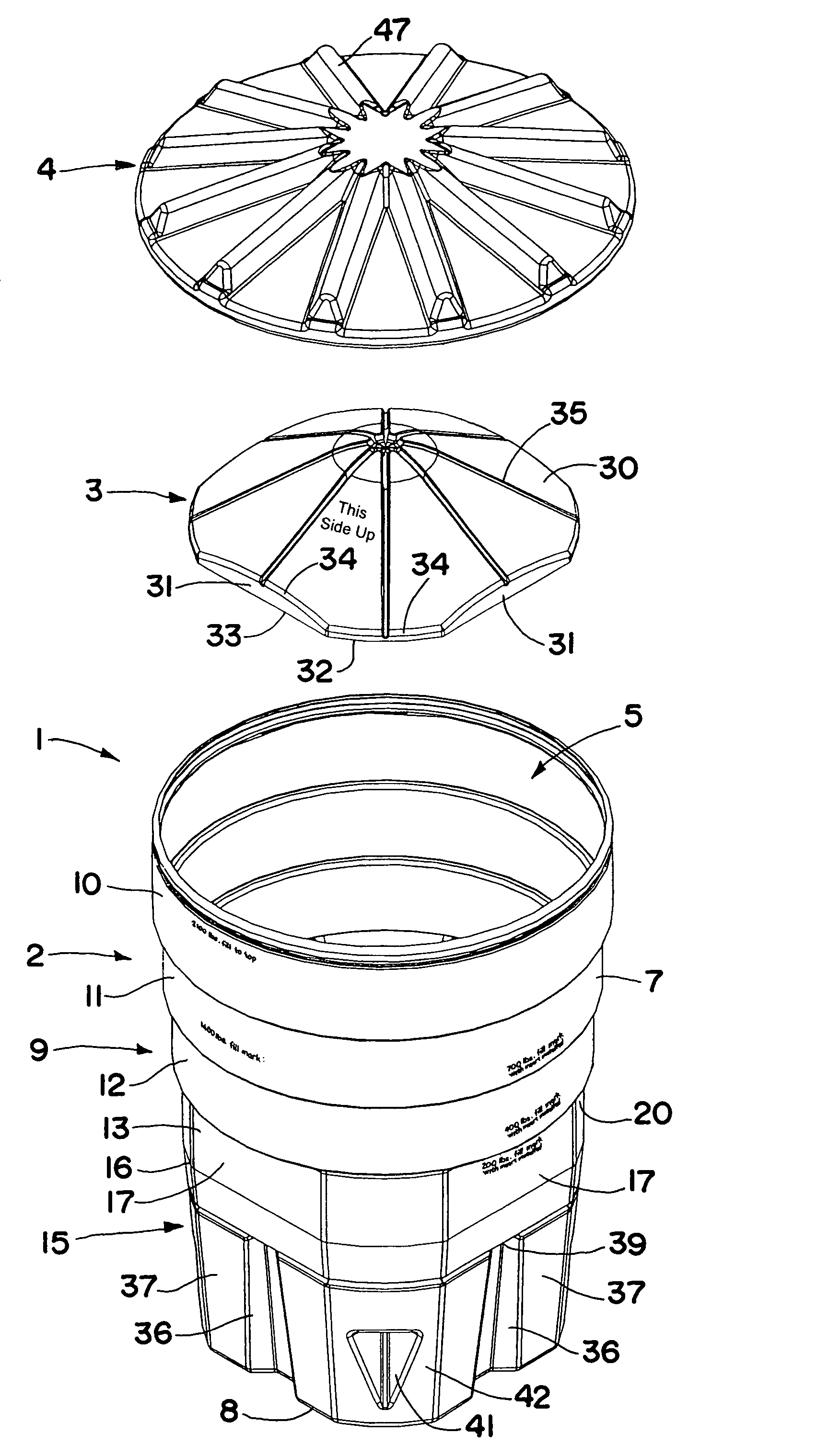
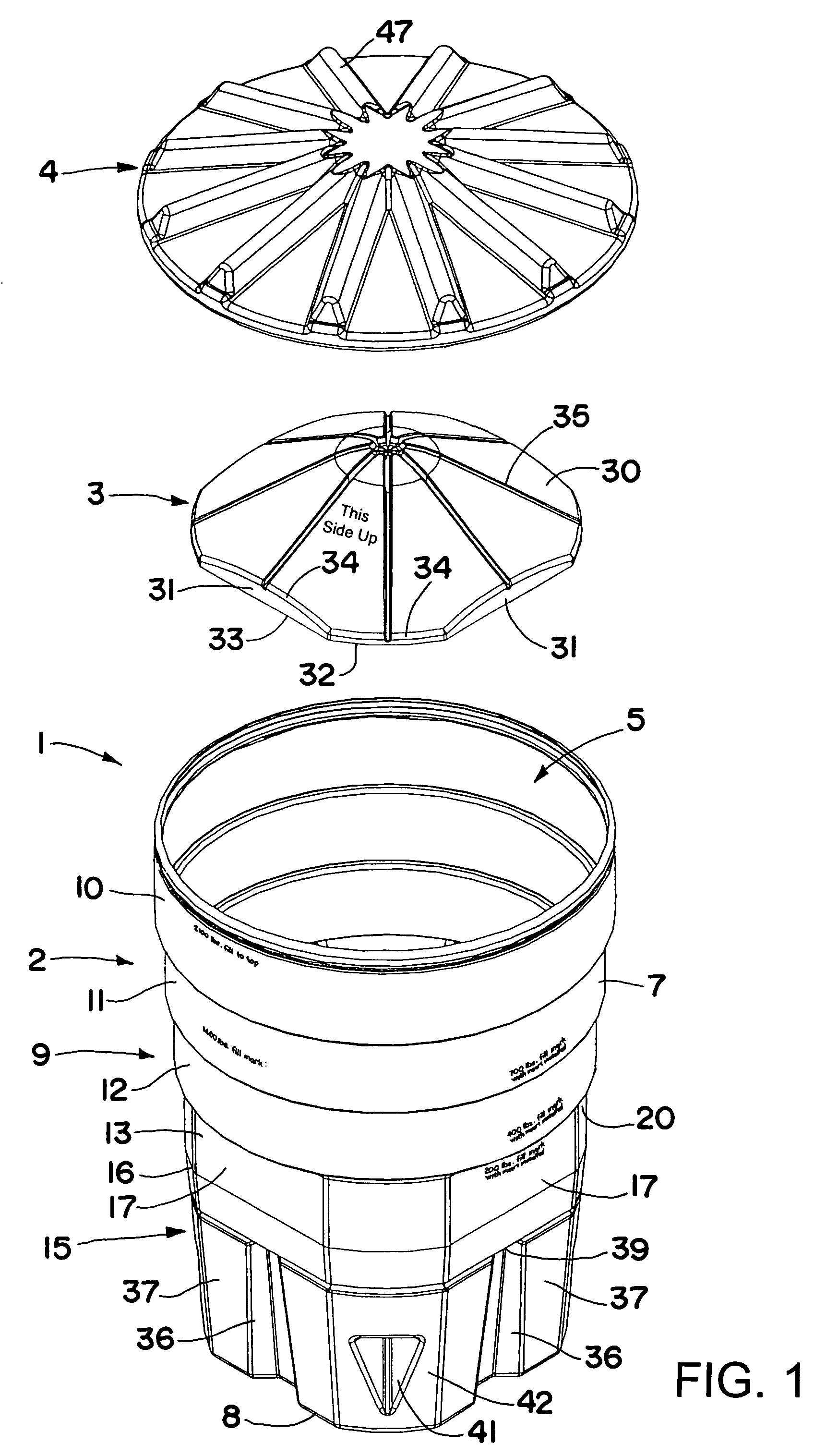
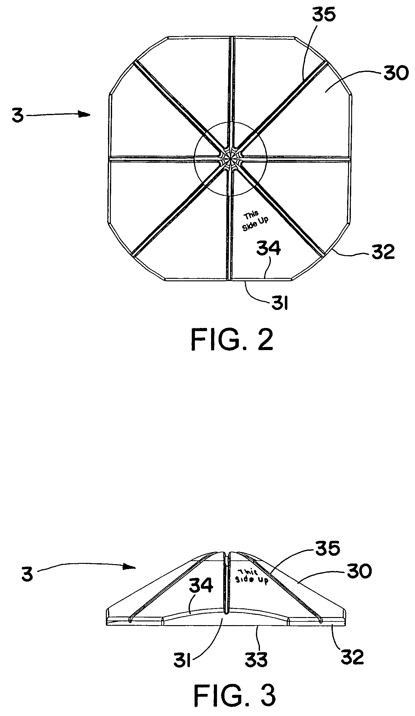
[0026]Referring now more particularly to the drawings, wherein like reference numerals are used to designate like parts, and initially to FIG. 1, there is shown one form of inertial barrier 1 of the present invention including an open top container 2, an insert 3 that is selectively positionable inside the container, and a cover or lid 4 that fits over the open top 5 of the container. When positioned inside the container, the insert 3 is supported by a ledge 6 (see FIG. 6) extending laterally inwardly from the container side wall 7 in spaced relation from the container bottom 8 and open top 5 for selectively supporting various amounts of sand (or other suitable dispersible granular energy absorbing material) above the insert to maintain the center of gravity of the barrier at about the same height as the bumper of an errant vehicle. All three of these elements may be molded out of a suitable plastic material such as high density polyethylene that is frangible or sufficiently deforma...


PUM


Abstract

An inertial barrier includes a standard size plastic container and a single size insert that is supported by a ledge inside the container for supporting different amounts of sand or other dispersible granular energy absorbing material thereon to achieve different barrier weight configurations. The insert has an axially upwardly, radially inwardly extending top wall that permits some downward flexing of the insert inside the container as the weight of the material that is placed on the insert builds up, causing the sides of the insert to expand and push radially outwardly against the container side wall, preventing the material from leaking past the insert inside the container. Axially extending ribs may be provided in the container side wall for increased strength and rigidity.

Description

FIELD OF THE INVENTION[0001]This invention relates generally to inertial barriers used to attenuate the energy of errant vehicles to limit their effects before striking an obstacle adjacent a roadway such as a bridge abutment or other roadway hazard.BACKGROUND OF THE INVENTION[0002]Arrays of inertial barriers have long been used to limit the effects of errant vehicles striking an obstacle such as a bridge abutment or other hazard adjacent a roadway. A typical inertial barrier system is comprised of an array of frangible plastic containers that are filled with varying amounts of sand or similar type dispersible granular energy absorbing material in a predetermined fashion so that should an errant vehicle crash into the barrier system, the vehicle will be caused to decelerate gradually hopefully with minimum damage to the vehicle and reduced risk of serious injury to its occupants. Barriers of progressively increased weight are typically employed in the direction toward the obstacle t...

Claims


Application Information

Patent Timeline
Patent Type & Authority Patents(United States)
IPC IPC(8): E01F13/00
CPCE01F15/146
Inventor METTLER, CHARLES M.BROWN, GREGORY H.
Owner PLASTIC SAFETY SYST
Why Eureka
Try Eureka