Electric switchgear

a switchgear and switch technology, applied in the direction of air-break switch, high-tension/heavy-dress switch, electrical apparatus, etc., can solve the problems manufacturing and installation costs, and the effect of increasing the complexity of the panel

Inactive Publication Date: 2012-10-09
ABB (SCHWEIZ) AG
View PDF16 Cites 13 Cited by
  • Summary
  • Abstract
  • Description
  • Claims
  • Application Information

AI Technical Summary

Benefits of technology

[0007]Therefore, it would be desirable to provide electric switchgear having an improved structure compared to known switchgear, and in particular, having an improved earthing switch with easy operation and with a reduced number of components, thereby reducing manufacturing and installation costs. The present invention is directed toward such an improved switchgear.

Problems solved by technology

Although known switchgear perform in a rather satisfying manner, there is still room for further improvements; for example, one usual drawback of actual switchgear resides in the fact that the main electrical components, i.e. the switching unit (be it a circuit breaker or a contactor) and the earthing switch are actuated substantially independent from each other and require dedicated manual or motor-operated actuation systems with a consequent increase of complexity of the panel, as well as manufacturing and installation costs thereof.

Method used


Image

  • Electric switchgear
  • Electric switchgear
  • Electric switchgear

Examples


Embodiment Construction

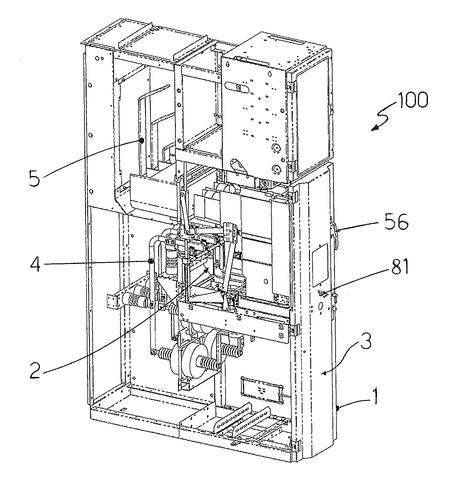
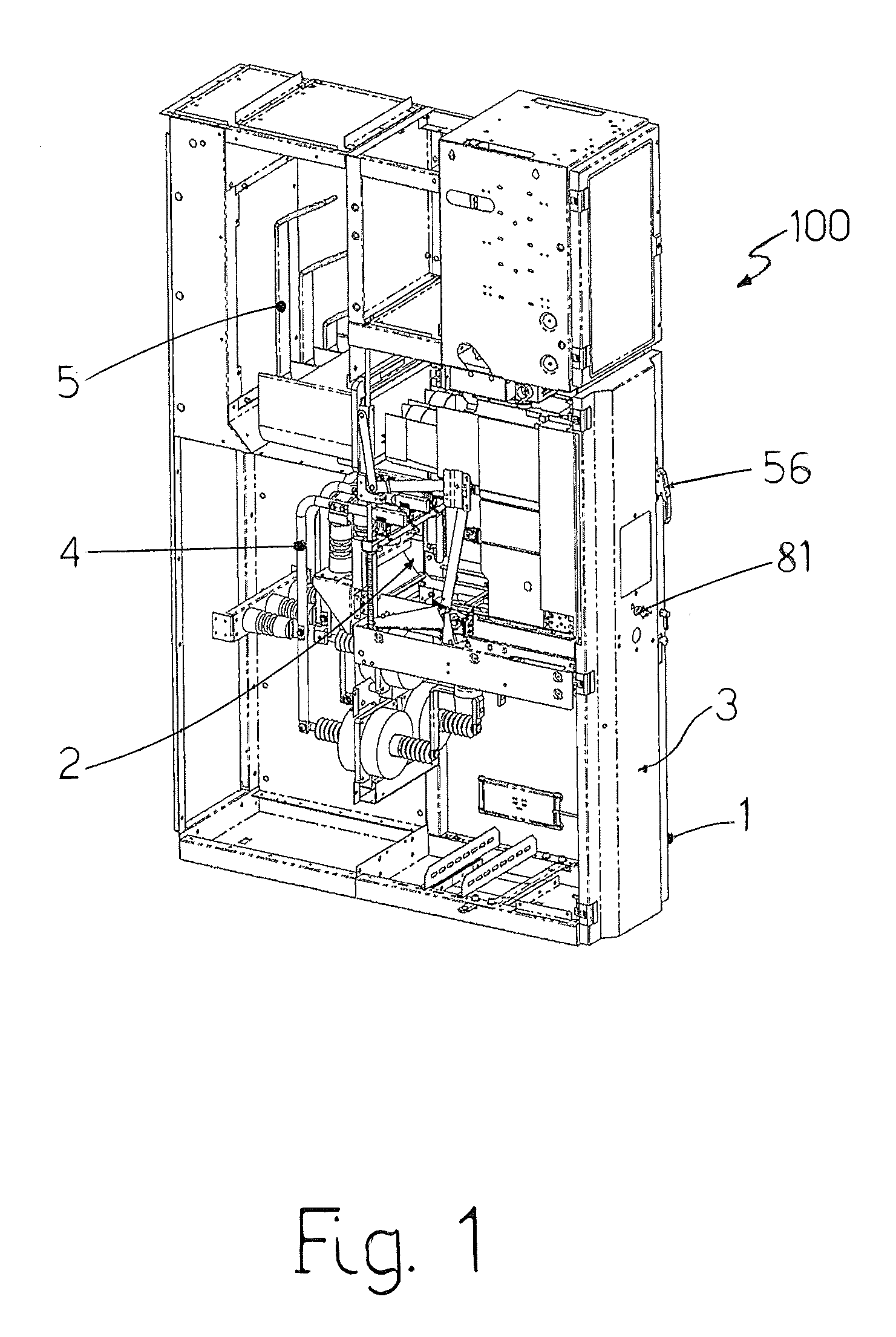
[0027]FIG. 1 shows an example of an electric switchgear according to the invention, indicated by the overall numeral reference 100, and represented in a preferred constructive embodiment, i.e. as a medium voltage motor control center (MCC).

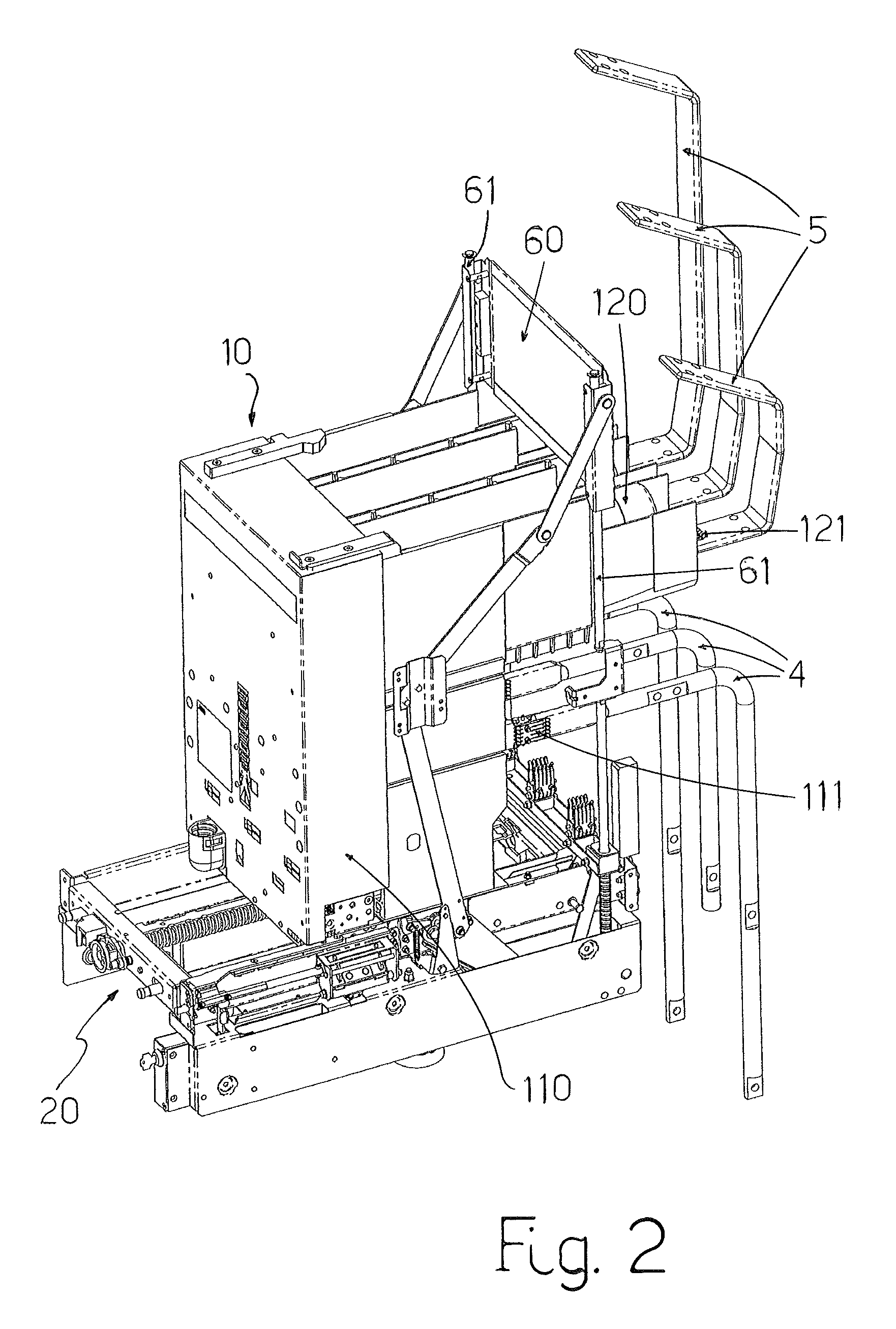
[0028]As illustrated, the switchgear or MCC 100 comprises a casing 1 having at least one compartment 2 provided with a door 3 for opening / closing the compartment 2; inside the compartment 2 there is provided a multi-phase switching device 10, preferably a withdrawable switching device, which is mounted on a movable truck 20, as illustrated in FIGS. 2-4.

[0029]According to a preferred embodiment, the switching device 10 comprises at least a current interruption device, preferably a multi-phase vacuum contactor 110, each phase of which is associated and electrically connected to a corresponding electric fuse 120; as known, each phase of the vacuum contactor comprises a couple of main contacts which can be electrically coupled to or separated from eac...


PUM


Abstract

Electric switchgear comprising a casing having at least one compartment provided with a door, a plurality of electrical conductors suitable to be connected to a load, a multi-phase switching device which is mounted on a truck movable inside the compartment between a connected position wherein each phase of the switching device is electrically connected to a corresponding electrical conductor and a withdrawn position wherein each phase of the switching device is electrically separated from the corresponding electrical conductor, and an earthing switch comprising a plurality of contacts for connecting to earth the plurality of electrical conductors. The earthing switch is actuated to move between a first position wherein each contact is electrically connected to a corresponding electrical conductor and a second position wherein each contact is electrically separated from the corresponding electrical conductor by the movement of the truck between the connected position and the withdrawn position.

Description

CROSS-REFERENCE TO RELATED APPLICATION[0001]This application claims priority under 35 U.S.C. §119(a)-(d) to European Patent Application Serial Number 09155700.9, filed on Mar. 20, 2009, the entire contents of which are hereby incorporated by reference.BACKGROUND OF THE INVENTION[0002]The present invention relates to an electric switchgear, which can be also indicated with the equivalent terms of electric panel, or electric switchboard, or similar definitions.[0003]The switchgear according to the present invention is particularly suitable for applications as a motor control center (MCC), preferably for medium voltage applications, i.e. for applications having a nominal voltage ranging between 1 kV and one or more tens of kV; hence, a particular reference to this application will be hereinafter made, without intending in any way to limit its possible further applications.[0004]Medium voltage switchgear or panels are well known in the art and they usually comprise a casing that is inte...

Claims


Application Information

Patent Timeline
Patent Type & Authority Patents(United States)
IPC IPC(8): H01H9/20
CPCH02B11/28H02B11/127
Inventor CAPELLI, FABIO
Owner ABB (SCHWEIZ) AG
Why Eureka
Try Eureka