
Vacuum interrupter switch for power distribution systems

a technology of current interrupter switch and power distribution system, which is applied in the direction of air break switch, high-tension/heavy-dress switch, electrical apparatus, etc., can solve problems such as environmental problems, and achieve the effect of minimizing potential hazards and ensuring safety and ecological effects

Inactive Publication Date: 2012-10-09
IMPACT POWER LLC A DELAWARE LLC
View PDF8 Cites 7 Cited by
  • Summary
  • Abstract
  • Description
  • Claims
  • Application Information

AI Technical Summary

Benefits of technology

"The invention is a vacuum interrupter switch that meets the requirements of utility demands and provides safety and ecological benefits. It allows for the replacement of existing paper-insulated lead cables with higher-rated synthetic cables. The switch is easy to install and fits through existing vault access holes. It is useful in higher voltage delta single-phase vacuum switch feeders with three branch circuits as a drop-in replacement for the lower voltage oil switches currently installed in the underground delta load centers, minimizing potential hazards. The invention is oriented in a specific way for clarity, but other orientations can be used. The materials used in the invention meet safety requirements and specifications for use with electric power lines. The patent text explains the technical effects of the invention and its benefits in replacing existing cables with higher-rated synthetic cables while minimizing potential hazards."

Problems solved by technology

At the same time, environmental and safety concerns have discouraged the use of such dielectric materials as oil and SF6 which can be flammable and / or explosive while presenting environmental problems when leakage occurs or when emissions are created.

Method used


Image

  • Vacuum interrupter switch for power distribution systems
  • Vacuum interrupter switch for power distribution systems
  • Vacuum interrupter switch for power distribution systems

Examples


Embodiment Construction

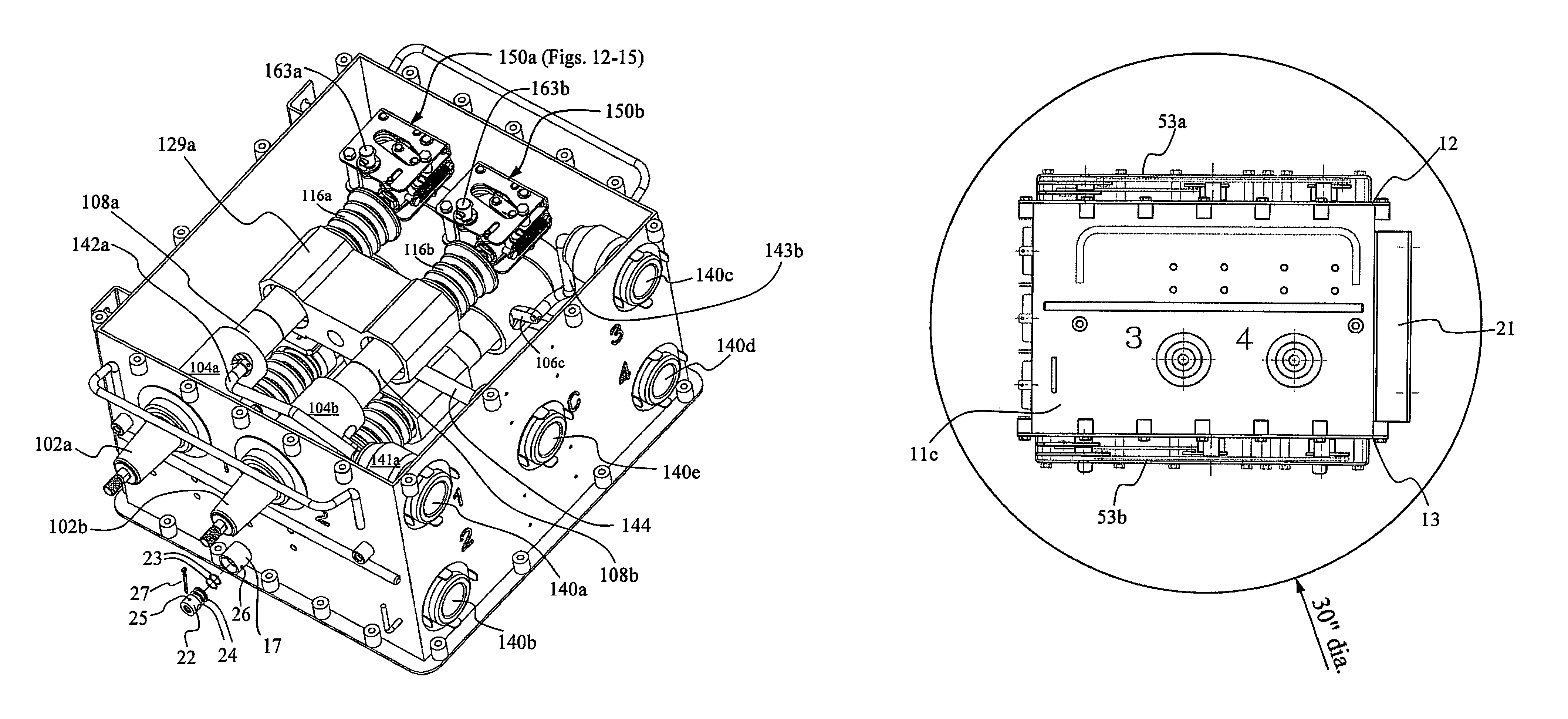
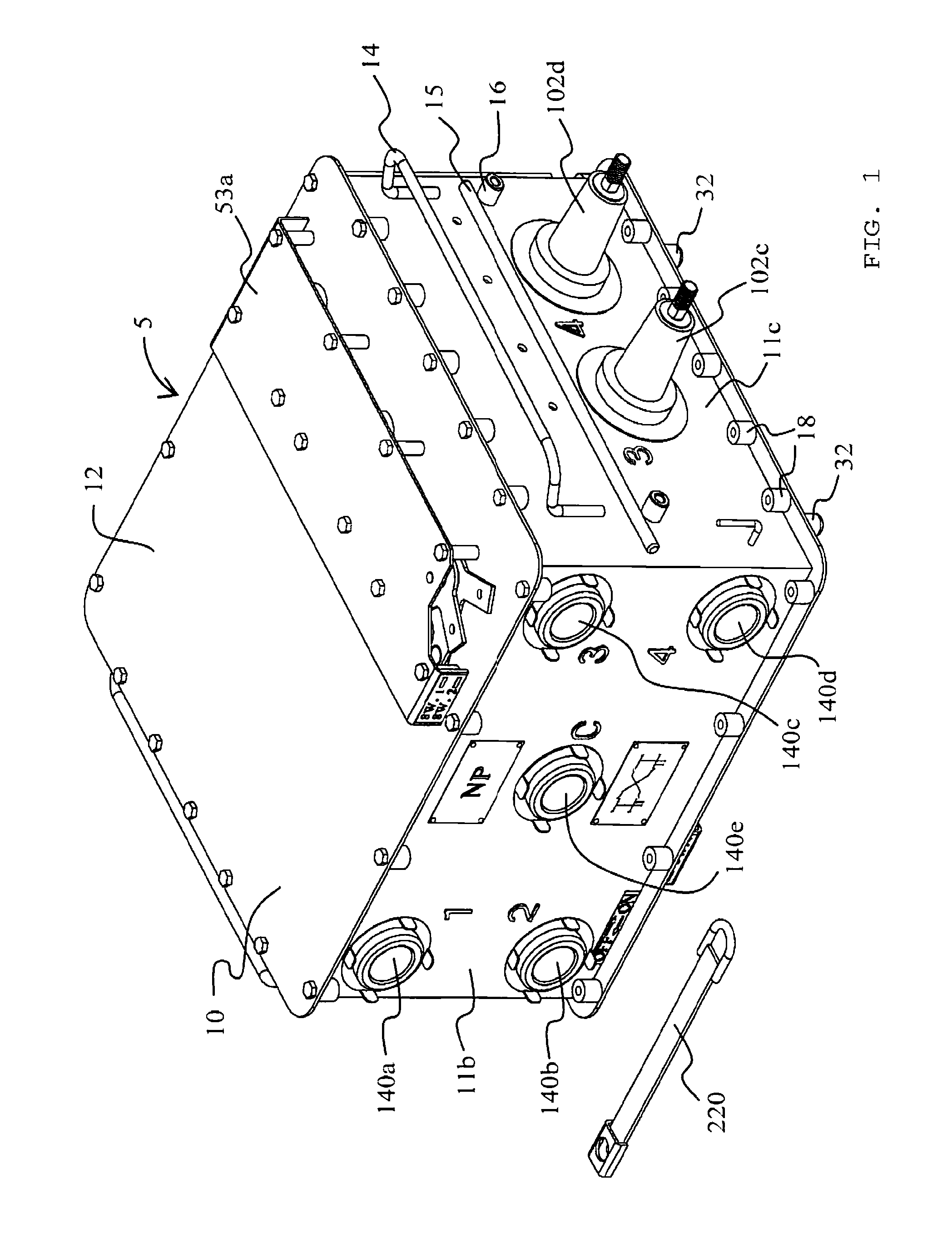
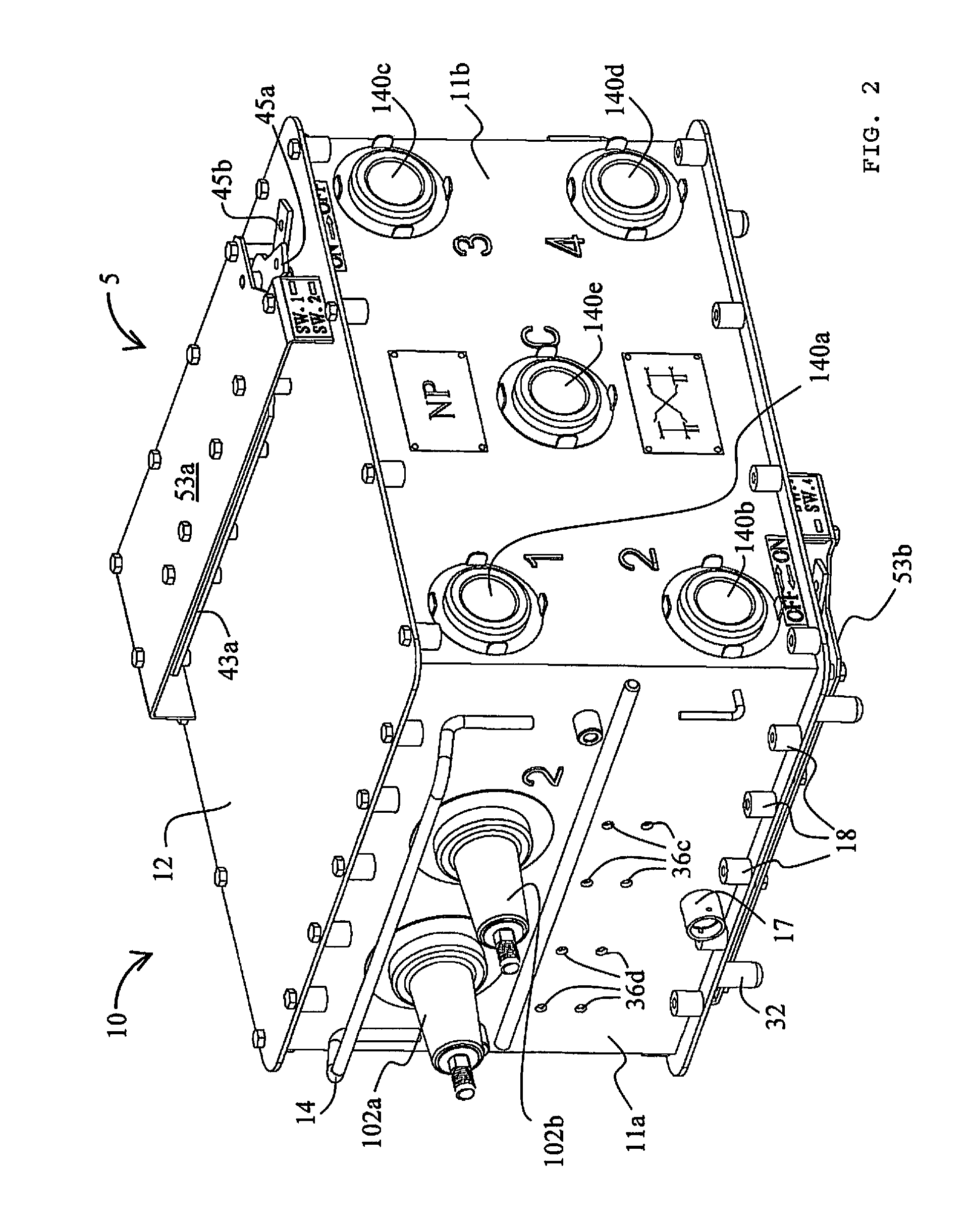
[0041]Referring to FIGS. 1-4, a vacuum interrupter switch assembly 5 constructed in accordance with the invention is illustrated. The assembly comprises of an outer case 10 with sidings 11a-d, lid 12, and bottom 13, formed from a sturdy, corrosive-resistant material. The preferred material is stainless steel. The dimensions of the case are preferably approximately 28.8 inches wide by 16.9 inches high by 21.5 inches deep to fit within existing access holes, such as the 30-inch diameter access hole illustrated in FIG. 11, and underground spaces available for switching assemblies. Each switch assembly case 10 is filled with dry air. Neither oil nor SF6 gas is used. The enclosed space may be filled with an electrically non-conductive moisture-resistant gel, if desired, once the assembly's internal components have been installed. The case 10 preferably has a welded lid 12.

[0042]A first pair of 600 amp power bushings 102a, 102b extends from siding 11a of case 10. A second pair of 600 amp ...


PUM


Abstract

A current interrupting switch for power distribution systems comprising an outer case and a plurality of vacuum interrupter bottle switches positioned in the case.

Description

CROSS REFERENCE TO RELATED APPLICATION[0001]This application claims priority of co-pending U.S. Provisional Patent Application No. 61 / 031,154, filed Feb. 25, 2008 which is incorporated by reference in its entirety herein and a copy of which is attached hereto as Exhibit A and made a part of this application. To the extent that there may be a conflict between the contents of the text and figures of Exhibit A and the text and figures which are not part of Exhibit A, the contents of the text and figures which are not part of Exhibit A shall govern.FIELD OF THE INVENTION[0002]The present invention pertains to current interrupting switches for power distribution systems. More particularly, the present invention relates to current interrupting switches for underground locations of power distribution systems.BACKGROUND[0003]Electric utility power distribution systems are frequently constructed underground for a variety of reasons ranging from objections to the above-ground aesthetics, the ...

Claims


Application Information

Patent Timeline
Patent Type & Authority Patents(United States)
IPC IPC(8): H01H9/02
CPCH01H33/666H01H33/53H01H33/6661H01H2033/566
Inventor HELLER, CARLHU, KUANG-CHIEN
Owner IMPACT POWER LLC A DELAWARE LLC
Learn More