Method of connecting chassis parts, and a chassis assembly

a chassis and chassis technology, applied in the direction of vehicle body-frame connection, vehicle cables, understructure, etc., can solve the problems of reducing the strength of the frame and the chassis at the connection site, deteriorating the overall strength of the chassis, and stress in the joining area of the components, so as to enhance the stability of the connection, increase the connection strength, and cross section

Inactive Publication Date: 2012-10-16
BENTELER AUTOMOBILTECHNIK GMBH
View PDF43 Cites 21 Cited by
  • Summary
  • Abstract
  • Description
  • Claims
  • Application Information

AI Technical Summary

Benefits of technology

[0008]It is, of course, conceivable to provide a seal between the end face of the first chassis part and the inner wall of the second chassis part. In this way, unevenness may, for example, be compensated. In any event, the space between the walls of the first and second chassis parts is completely sealed in the overlap zone with respect to the fluid.
[0026]The connection between two or more chassis parts through application of the internal high pressure joining process causes little stress and causes no warping due to heat or an adverse effect on the corrosion resistance of the components. The connection between the chassis parts is able to withstand torsional and bending stress and includes an interference fit as well as a form fit. The connection is easy to make and can easily be suited to different chassis parts.

Problems solved by technology

Thermal joining, such as welding, causes however problems in the connection zone as far as durability and corrosion resistance of the connection are concerned.
In addition, stress is caused in the components in the joining area as a result of warping due to heat exposure.
This decreases the strength of the frame and the chassis at the connection sites so that the overall strength of the chassis deteriorates.
Also, the combination of various materials, such as aluminum and steel is rather limited when using thermal joining processes.

Method used


Image

  • Method of connecting chassis parts, and a chassis assembly
  • Method of connecting chassis parts, and a chassis assembly
  • Method of connecting chassis parts, and a chassis assembly

Examples


Embodiment Construction

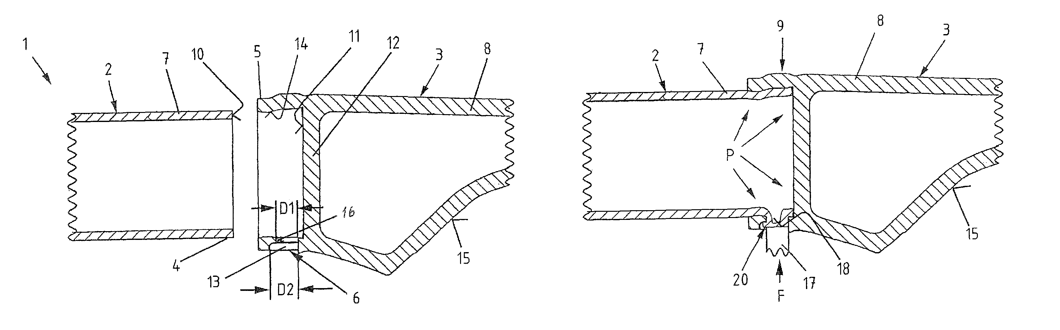
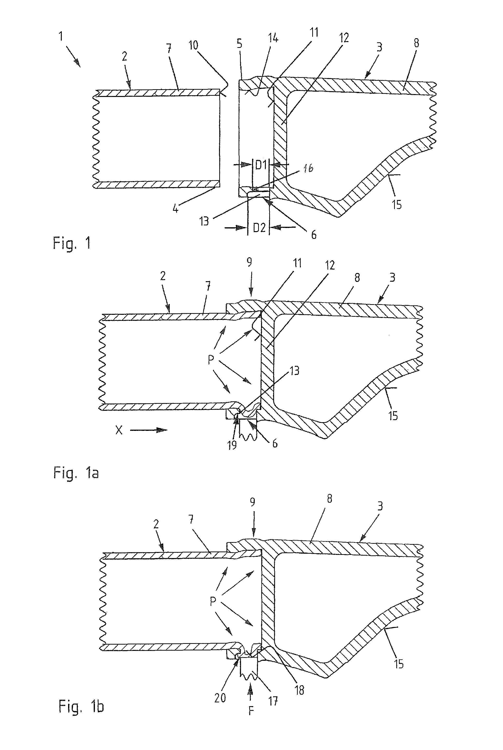
[0031]Throughout all the figures, same or corresponding elements may generally be indicated by same reference numerals. These depicted embodiments are to be understood as illustrative of the invention and not as limiting in any way. It should also be understood that the figures are not necessarily to scale and that the embodiments are sometimes illustrated by graphic symbols, phantom lines, diagrammatic representations and fragmentary views. In certain instances, details which are not necessary for an understanding of the present invention or which render other details difficult to perceive may have been omitted.

[0032]Turning now to the drawing, and in particular to FIGS. 1, 1a, 1b, there are shown sectional views of successive steps of a method of connecting chassis parts in accordance with the present invention. FIG. 1 shows two chassis parts 2, 3 in their starting position with their ends 4, 5 confronting one another. The chassis part 2 is constructed as hollow section and the ch...


PUM

PropertyMeasurementUnit
pressureaaaaaaaaaa
diameteraaaaaaaaaa
weightaaaaaaaaaa

Abstract

In a method of connecting chassis parts to produce a chassis assembly, at least one end of a first chassis part is connected with a second chassis part in an overlap zone by a form fit and an interference fit through an internal high pressure joining process. The second chassis part serves hereby a seal of the one end of the first chassis element.

Description

CROSS-REFERENCES TO RELATED APPLICATIONS[0001]This application claims the priority of German Patent Application, Serial No. 10 2008 038 276.0, filed Aug. 18, 2008, pursuant to 35 U.S.C. 119(a)-(d), the content of which is incorporated herein by reference in its entirety as if fully set forth herein.BACKGROUND OF THE INVENTION[0002]The present invention relates to a method of connecting chassis parts, and to a chassis assembly comprised of connected chassis parts.[0003]The following discussion of related art is provided to assist the reader in understanding the advantages of the invention, and is not to be construed as an admission that this related art is prior art to this invention.[0004]Many frame elements as well as chassis elements are connected together in the automobile industry through thermal joining processes. To reduce weight of motor vehicles, the frame and chassis elements are partly or entirely configured as hollow sections and welded together, in part with cast nodes a...

Claims


Application Information

Patent Timeline
Patent Type & Authority Patents(United States)
IPC IPC(8): B21D39/04B21D26/035
CPCB21D26/035B60G21/051B62D21/11B62D29/008B21D39/04Y10T29/49936B60G2206/20B60G2206/8209B60G2206/83Y10T29/4994Y10T29/49915Y10T29/49945Y10T29/49911Y10T29/49805Y10T403/49Y10T29/49622
Inventor STOLLE, JENSVOIGT, DIRKBEER, FRANZ
Owner BENTELER AUTOMOBILTECHNIK GMBH
Why Eureka
Try Eureka