Milk liner

a technology of milk liner and udder, which is applied in the field of milk liner, can solve the problems of milk liner creeping along the teat towards the cow's udder, increasing the and extra weight of milking clusters

Active Publication Date: 2012-10-16
DAIRYMASTER
View PDF7 Cites 0 Cited by
  • Summary
  • Abstract
  • Description
  • Claims
  • Application Information

AI Technical Summary

Benefits of technology

[0025]By providing the strengthening means extending axially from the sleeve and terminating in an abutment surface for abutting the udder, a further advantage of the invention is provided in that even should the milk liner assembly creep upwardly along the teat, when the abutment surface of the strengthening means abuts the udder of the animal, the strengthening means spaces the teat engaging flange a sufficient distance from the udder in order to prevent engagement of the teat engaging flange with the cricoid fold.
[0026]The provision of the strengthening means on the sleeve, as opposed to locating the strengthening means on the teat engaging flange has the further advantage that the strengthening means provides all the strength necessary for minimising excessive inward radial contraction of the teat engaging flange onto the teat, while at the same time permitting axial deflection of the teat engaging flange.

Problems solved by technology

One problem with such milk liner assemblies is that during periods of no vacuum in the annular vacuum chamber around the milk liner between vacuum pulses during each pulsating vacuum cycle, when the milk liner is tightly urged into engagement with the teat, the milking vacuum applied to the teat receiving cavity tends to draw the teat into the teat receiving cavity, thus causing the milk liner to creep along the teat towards the cow's udder.
This causes serious problems during milking, particularly when the milk liner assembly has crept along the teat to the extent that the teat engaging flange at the end of the milk liner commences to engage the cricoid fold at the root of the teat where it extends from the udder.
However, increasing the weight of a milking cluster is undesirable, since firstly, there is no guarantee that the extra increase in weight will be sufficient for preventing creep of the milk liner along the teat, and secondly, the extra weight of the milking cluster militates against efficient milking, particularly where a large number of cows are to be milked, since the extra weight reduces the speed at which the milking clusters can be attached to and detached from the teats of the cows.
This, in general, is impractical.

Method used


Image

  • Milk liner
  • Milk liner
  • Milk liner

Examples


Embodiment Construction

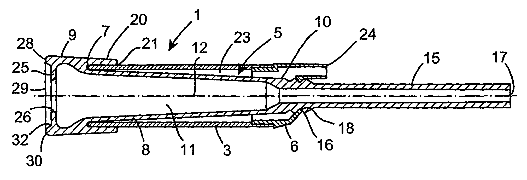
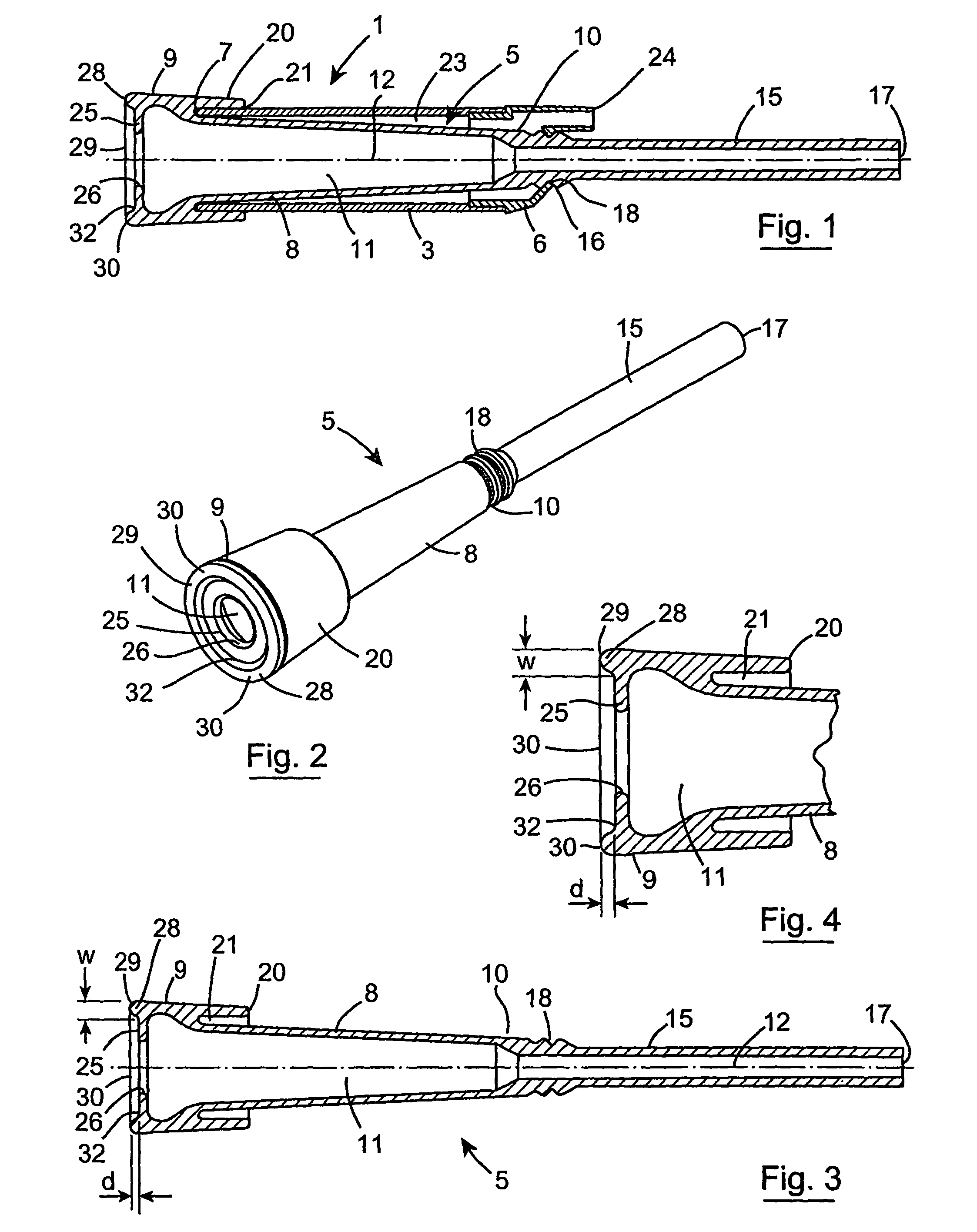
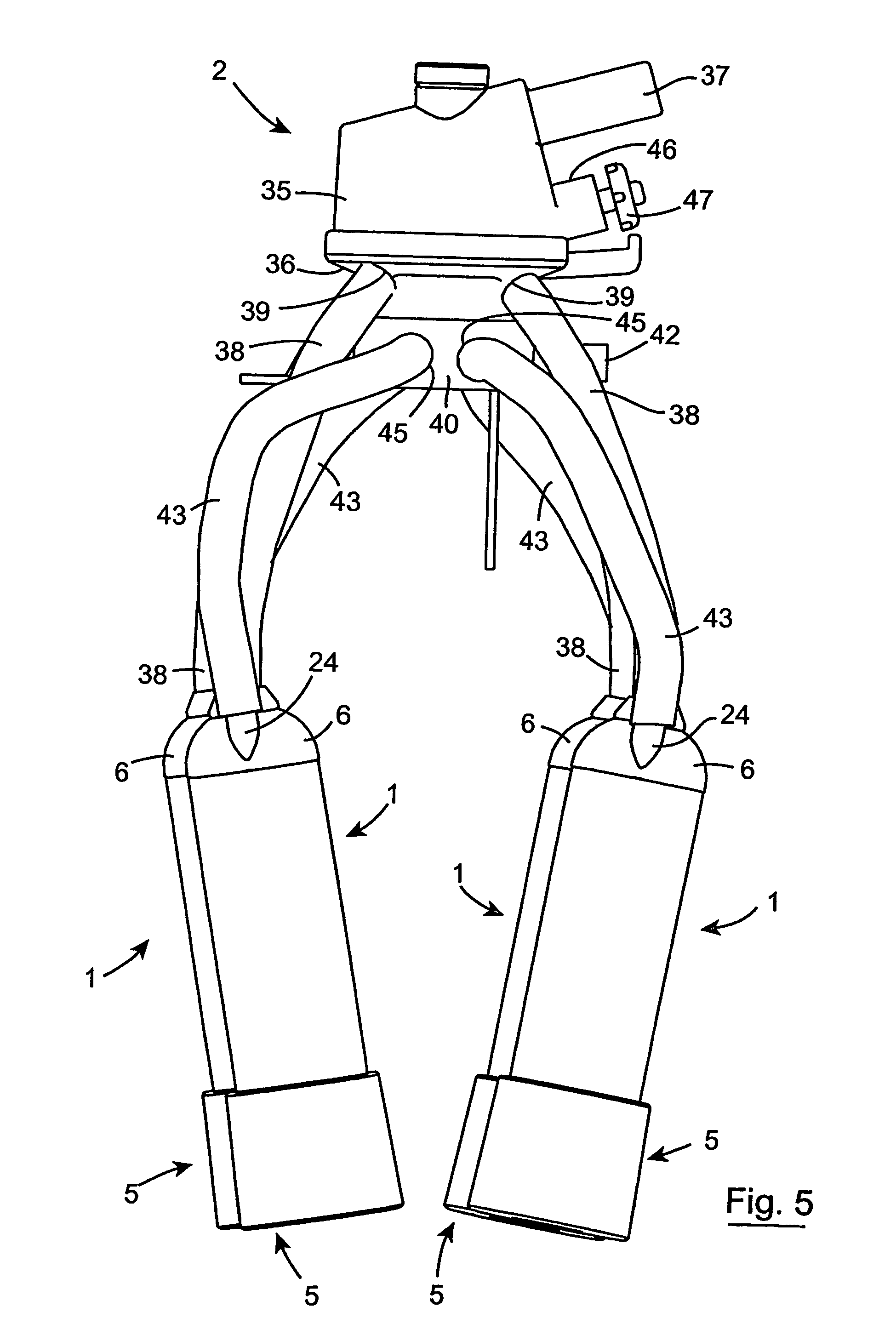
[0033]Referring to the drawings, there is illustrated a milk liner assembly according to the invention, indicated generally by the reference numeral 1 of a milking cluster 2 also according to the invention for a vacuum operated milking system (also not shown). In this embodiment of the invention the milk liner assembly 1 and the milking cluster 2 are suitable for milking cows. As will be described below with reference to FIG. 5, each milking cluster 2 comprises four milk liner assemblies 1, one for attaching to each teat of a cows udder. Such vacuum operated milking systems will be well known to those skilled in the art, and further description of such systems should not be required.

[0034]The milk liner assembly 1 comprises an outer shell 3 typically of stainless steel material, and a milk liner also according to the invention, indicated generally by the reference numeral 5, located within the outer shell 3. The outer shell 3 is of circular transverse cross-section, and terminates a...


PUM


Abstract

A milk liner assembly (1) comprises a milk liner (5) seal ably located in an outer shell (3) and defining with the outer shell (3) a pulsating vacuum chamber (23). The milk liner (5) comprises a sleeve (8) and a teat engaging flange (25) which together define a teat receiving cavity (11). A teat accommodating opening (26) through the teat engaging flange (25) accommodates a teat into the teat receiving cavity (11). A strengthening ring (28) integrally formed with the sleeve (8) is located on the sleeve (8) and extends around the sleeve (8) adjacent the teat engaging flange (25) for minimizing excessive radial inward contraction of the sleeve (8), and in turn excessive radial inward contraction of the teat engaging flange (25) onto the teat so that even if the teat engaging flange (25) were to engage the cricoid fold, milk flow through the cricoid fold would not be inhibited by the gripping pressure exerted the teat engaging flange (25) on the cricoid fold. The strengthening ring (28) extends axially from the sleeve (8), and terminates in a distal abutment surface (30) for abutting the udder of the animal for in turn spacing the teat engaging flange (25) from the udder and from the cricoid fold.

Description

[0001]This is a National Stage entry of International Application PCT / IE04 / 00073, with an international filing date of May 17, 2004, which was published as WO 2004 / 100651 A1, and the complete disclosure of which is incorporated into this application by reference.BACKGROUND OF THE INVENTION [0002]The present invention relates to a milk liner for a milk liner assembly of an animal milking system, and in particular, though not limited to a milking system for milking cows. The invention also relates to a milk liner assembly, as well as to a milking cluster for use in a milking system, and the invention relates to a method for minimising excessive radial inward contraction, during milking of an animal, of a teat engaging flange of a milk liner onto a teat of an animal passing therethrough.[0003]Milk liner assemblies for use in milking systems for milking cows are provided in groups of four which are commonly referred to as a milking cluster. Each milk liner assembly of the cluster is pro...

Claims


Application Information

Patent Timeline
Patent Type & Authority Patents(United States)
IPC IPC(8): A01J5/04A01J5/00A01J5/08A01J5/16
CPCA01J5/08
Inventor HARTY, SR., EDMOND PATRICKHARTY, JR., EDMOND PATRICK
Owner DAIRYMASTER
Why Eureka
Try Eureka