Tire parameter monitoring system with sensor location using RFID tags

a technology of tire parameter and monitoring system, which is applied in the direction of tire measurement, vehicle components, transportation and packaging, etc., can solve the problems of system re-correlation, required installation of separate interrogation antennae adjacent to tire parameter sensor units, and inconvenient installation and maintenance. , to achieve the effect of high reliability, simple and inexpensive implementation, and accura

Inactive Publication Date: 2012-10-16
SILICON VALLEY MICRO C
View PDF8 Cites 21 Cited by
  • Summary
  • Abstract
  • Description
  • Claims
  • Application Information

AI Technical Summary

Benefits of technology

[0013]The invention comprises a method and system for providing sensor unit location information using permanently mounted RFID tags mounted adjacent tire locations on a vehicle, which is simple and inexpensive to implement, highly reliable, and accurate.

Problems solved by technology

A disadvantage with this type of location correlation technique is that any change to the original tire and sensor unit location requires that the system be re-correlated.
While some vehicle owners may be capable of acquiring the necessary skill and training, others may not.
The latter will necessarily suffer delay and expense when re-configuring the vehicle tires and wheels; the former will suffer at least the delay attendant upon re-familiarizing oneself with the steps required to re-program an electronic system.
A disadvantage to the interrogator antenna system described above lies in the requirement for the installation of the separate interrogation antennae adjacent the tire parameter sensor units.
As a consequence, installation cost and hardware durability are factors of concern when deciding to implement such a system.
While highly effective, the functioning of the magnetic field arrangement described above can be impaired in highly ferro-magnetic environments, which can distort the magnetic fields.
Efforts to provide a simple, inexpensive, reliable, and accurate sensor unit location feature for a tire parameter sensing system devoid of the above-noted disadvantages have not been successful to date.

Method used


Image

  • Tire parameter monitoring system with sensor location using RFID tags
  • Tire parameter monitoring system with sensor location using RFID tags
  • Tire parameter monitoring system with sensor location using RFID tags

Examples


first embodiment

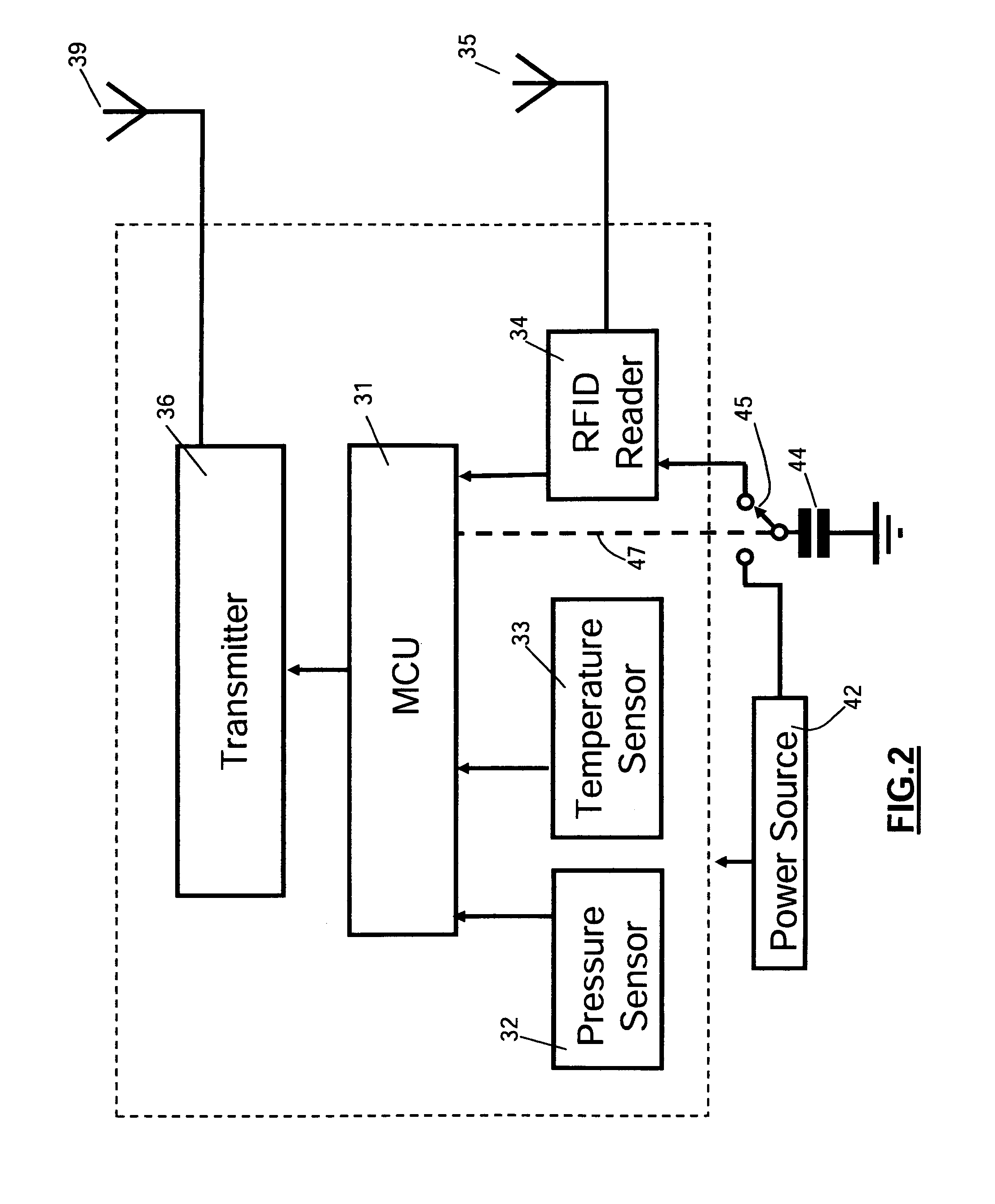
[0039]With reference to FIG. 2., which is a schematic block diagram of a sensor unit having a battery power source, each sensor unit SU 12, 14, 16, and 18 incorporates a microcontroller unit 31 for processing sensor signals from one or more tire parameter sensors, such as tire pressure sensor 32 and tire internal temperature sensor 33. Microcontroller unit 31 also controls the operation of an RFID tag reader 34 and an r.f. transmitter unit 36. RFID reader 34 interrogates the associated RFID tag reader via an antenna 35 and supplies the RFID tag identification code to microcontroller unit 31 when directed to by microcontroller 31. RFID reader is preferably a type RI-RFM-003B mini radio frequency module available from Texas Instruments Incorporated or the equivalent. Microcontroller unit 31 may comprise any one of a number of known units, such as a commercially available Freescale type MC68HC908RF2 unit or the equivalent, having a transmitter section for generating r.f. information si...

second embodiment

[0042]FIG. 5 is a schematic block diagram of a sensor unit having an electromagnetic inductive power source. As seen in this Fig., the sensor unit includes microcontroller 31, sensors 32, 33, RFID tag reader 34, RFID tag reader antenna 35, transmitter 36, and antenna 37. In addition, the sensor unit of FIG. 5 includes a power coil 61 and a power system 62. Elements 31-37, 61 and 62 are all carried by a substrate which is preferably fabricated from a relatively thin, flexible dielectric material, such as PTFE, possessing good bonding characteristics for the system components 31-37, 61, and 62 and capable of good adhesion to the outer or inner wall surface of a vehicle tire or compatible with internal mounting within a tire side wall. Power coil 61 and power system 62 are constructed and function in a manner essentially identical to that disclosed in the above-referenced U.S. Pat. No. 7,363,806, the disclosure of which has been incorporated by reference. Briefly, power coil 61 generat...


PUM


Abstract

A tire parameter monitoring system has a plurality of sensor units for monitoring tire parameters, with each sensor unit mounted with a different vehicle tire. Each sensor unit has an RFID tag reader for interrogating an RFID tag securely mounted to the vehicle adjacent the corresponding tire and containing a unique identification code. Each sensor unit has a microcontroller for combining each RFID identification code with corresponding tire parameter signals, and a transmitter for transmitting the combined signals to a receiving location. Received tire parameter signals are correlated with the tire location using the RFID identification code, and driver advisory signals are presented to the driver by a display / alarm unit. Two alternative power supplies are provided. A first type uses a battery and a power management circuit for eliminating power drain when the RFID tag reader is energized. A second type uses inductive power to provide an inexhaustible power source.

Description

BACKGROUND OF THE INVENTION[0001]This invention relates to vehicle tire parameter monitoring systems. More particularly, this invention relates to a tire parameter monitoring system having a sensor unit position location feature using RFID tags.[0002]Tire parameter monitoring systems are known and are commonly used to monitor one or more parameters of interest in individual pneumatic tires of a vehicle and to provide an advisory signal to the driver, usually via an on-board computer system, containing information about the tire parameter(s). The portion of the tire parameter monitoring system located at or in the individual tires is termed the sensor unit, and includes one or more sensors capable of measuring the parameter(s) of interest and generating an electrical signal representative of the value of the measurement, a signal generator (typically an r.f. signal generator) capable of generating a wireless signal corresponding to the electrical signal, a microcontroller (such as a ...

Claims


Application Information

Patent Timeline
Patent Type & Authority Patents(United States)
IPC IPC(8): B60C23/00B60C23/02
CPCB60C23/041B60C23/0413B60C23/0416B60C23/045
Inventor ZHU, SHENGBOHUARG, SU SHIONG
Owner SILICON VALLEY MICRO C
Why Eureka
Try Eureka