Display device and method for driving display device

a display device and display device technology, applied in the field of display devices, can solve the problems of inability to resume the power supply to the inverter circuit, difficulty for users or operators to identify blown fluorescent tubes, and inability to maintain the power supply in the on-state state, so as to facilitate the identification of blown fluorescent tubes and efficient maintenance work

Inactive Publication Date: 2012-10-16
SHARP KK
View PDF17 Cites 4 Cited by
  • Summary
  • Abstract
  • Description
  • Claims
  • Application Information

AI Technical Summary

Benefits of technology

[0014]The present invention has been made in view of the foregoing problems, and it is an object of the present invention to, in a display device in which a backlight constituted by a plurality of fluorescent tubes is used, make maintenance work more efficient by identifying a failed fluorescent tube while the backlight is not lighting.
[0018]For example, in cases where one of the plurality of fluorescent tubes has blown while the display device is being driven in the normal mode, the inverter section is stopped, whereby all the fluorescent tubes stop lighting and the display panel stops displaying anything. At this point, the user or operator switches from the normal mode to the maintenance mode to carry out maintenance work or, specifically, an operation for identifying and replacing the blown fluorescent tube, the inverter section is driven again, whereby all the normal fluorescent tubes start lighting except for the blown fluorescent tube. This enables the user or operator to easily identify the blown fluorescent tube with his / her eyes. This makes it unnecessary to inspect the plurality of fluorescent tubes by removing them or inspect them with use of a measuring instrument, thus enabling efficient maintenance work.
[0019]Further, in the maintenance work, the failed fluorescent tube can be visually identified; therefore, the work does not need to be carried out with hands touching the components of the backlight. For this reason, conventional dangers such as an electric shock can be avoided.
[0021]According to the foregoing configuration, in cases where the inverter section is driven again in the maintenance mode at the time of a failure in the backlight, the display panel displays a white display screen image, whereby a black line indicative of the location of the failed fluorescent tube appears in the white display screen image. This makes it possible to identify the failed fluorescent tube among the plurality of fluorescent tubes.
[0024]On receipt of the backlight failure signal, the foregoing configuration notifies outside that the backlight has failed. This allows the user or operator to surely grasp whether or not the backlight has failed, thus enabling more efficient maintenance work.
[0026]On receipt of the backlight failure signal, the foregoing configuration notifies outside that the backlight has failed, and in cases where the driving mode is the maintenance mode, the foregoing configuration notifies outside that the driving mode is the maintenance mode is made. This allows the user or operator to confirm that his / her driving-mode switching operation has been surely accepted. In particular, since it can be confirmed that a shift has been surely made to the maintenance mode at the time of a failure in the backlight, an improvement in safety of maintenance work can be achieved.

Problems solved by technology

However, since the protection circuit is still working, the supply of power to the inverter circuit is not resumed, and the liquid crystal panel remains to display nothing.
Moreover, in the end, when the number of consecutive times the power supply is turned on reaches a predetermined value, even the power supply becomes unable to be in an on-state, because the protection circuit usually has a counter function.
This makes it difficult for the user or operator to identify a blown fluorescent tube in performing an operation for replacing a failed fluorescent tube.
In particular, since a recent increase in size of a display panel has been accompanied by an increase in the number of fluorescent tubes constituting a backlight, the amount of time required to replace one fluorescent tube with another is undesirably increased.

Method used


Image

  • Display device and method for driving display device
  • Display device and method for driving display device
  • Display device and method for driving display device

Examples


example 1

[0096](Operation Example 1 of the Liquid Crystal Display Device 10)

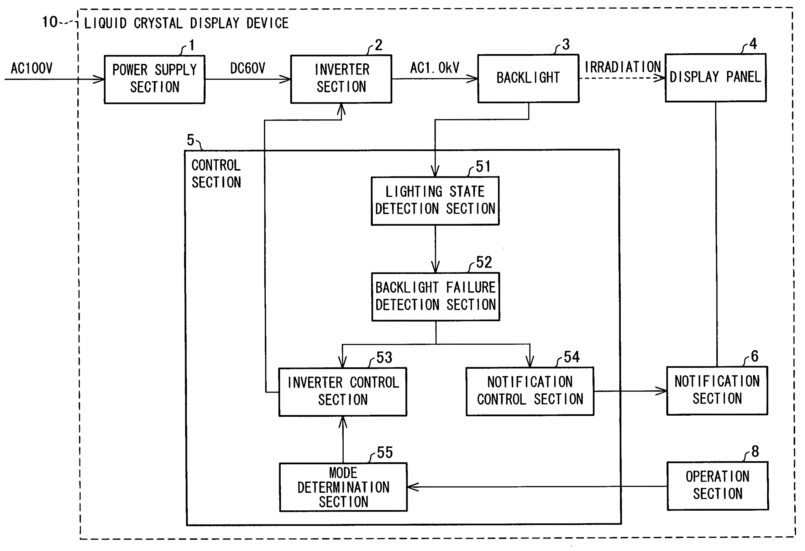
[0097]The following deals with the functions of the respective sections of the liquid crystal display device 10 with reference FIGS. 1 and 5 together with their specific operations. FIG. 5 is a process flow chart showing an operation that the liquid crystal display device 10 performs.

[0098]First, in Step 11 (hereinafter abbreviated as in “S11”) of FIG. 5, after the power supply section 1 is externally supplied with AC 100 V, the power supply section 1 supplies the inverter section 2 with driving electric power (voltage) which causes the inverter section 2 to be driven, and the inverter section 2 converts the voltage into a backlight-driving alternating voltage and outputs it to the backlight 3. Next, the lighting state detection section 51 detects whether the backlight 3 is lighting or not lighting, and then outputs a detected result to the backlight failure detection section 52 (S12).

[0099]Upon receiving, from the l...

example 2

[0105](Operation Example 2 of the Liquid Crystal Display Device 10)

[0106]The following describes a configuration for more easily identifying a failed fluorescent tube such a blown one. In Operation Example 2, the liquid crystal display device 10 is configured to include the panel control section 56, which performs display control of the display panel 4 at the time of the maintenance mode, in addition to the configuration in Operation Example 1 where the inverter section 2 is forcibly driven at the time of the maintenance mode.

[0107]Specifically, the liquid crystal display device 10 is configured such that when the inverter section 2 is forcibly driven at the time of the maintenance mode, the panel control section 56 controls the display panel 4 so that the display panel 4 displays a white display screen image. This configuration is described below with reference to FIGS. 7 and 8 together with specific operation.

[0108]FIG. 8 is a process flow chart showing an operation that the liqui...

example 3

[0113](Operation Example 3 of the Liquid Crystal Display Device 10)

[0114]The following describes another example of operation of the liquid crystal display device 10. In Operation Example 3, the liquid crystal display device 10 is configured such that the notification section 6 notifies outside of whether the current driving mode is the normal mode or the maintenance mode, in addition to the configuration in Operation Example 1.

[0115]Specifically, the liquid crystal display device 10 is configured such that in response to a result of determination from the mode determination section 55, the notification control section 54 commands the notification section 6 to notify outside of whether the driving mode is the normal mode or the maintenance mode. This configuration is described below with reference to FIGS. 10 and 11 together with specific operation.

[0116]FIG. 11 is a process flow chart showing an operation that the liquid crystal display device 10 performs in notifying outside of th...


PUM


Abstract

One embodiment of the present invention discloses a transmissive display device including a display panel, a backlight including a plurality of fluorescent tubes, an inverter section that supplies a driving voltage to the backlight, and an inverter control section that controls whether to drive or stop the inverter section and stops the inverter section when at least one of the fluorescent tubes is not lighting. The display device includes a mode determination section that determines whether a driving mode of the display device is a normal mode or a maintenance mode. Upon receiving, from the mode determination section, a signal indicating that the drive mode is the maintenance mode, after having stopped the inverter section due to a fact that at least one of the plurality of fluorescent tubes is not lighting, the inverter control section drives the inverter section again. Such a configuration makes it possible to, in a display device in which a backlight including a plurality of fluorescent tubes is used, make maintenance work more efficient by identifying a failed fluorescent tube while the backlight is not lighting.

Description

TECHNICAL FIELD[0001]The present invention relates to a display device such as a transmissive liquid crystal display device and a method for driving a display device.BACKGROUND ART[0002]There are various types of color displays that have been in practical use. Thin displays are classified broadly into (i) self-luminous displays such as PDPs (plasma display panels) and (ii) nonluminous displays typified by LCDs (liquid crystal displays). A known example of an LCD, i.e., a nonluminous display is a transmissive LCD having a backlight disposed on the back surface side of a liquid crystal panel.[0003]FIG. 14 is a cross-sectional view illustrating a typical structure of a transmissive LCD. This transmissive LCD has a backlight 110 disposed on the back surface side of a liquid crystal panel 100. The liquid crystal panel 100 includes: a pair of transparent substrates 101 and 102; a liquid crystal layer 103 disposed between the transparent substrates 101 and 102; and polarizing plates 104 an...

Claims


Application Information

Patent Timeline
Patent Type & Authority Patents(United States)
IPC IPC(8): G09G3/36
CPCG09G3/006G09G3/342G02F1/133604G09G2320/0606G09G2330/02G09G2330/04
Inventor NANBU, KOHEI
Owner SHARP KK
Why Eureka
Try Eureka