
Method and apparatus for complex impedance compensation

a complex impedance compensation and complex technology, applied in the field of complex impedance compensation, can solve the problems of inaccurate reading that is not completely indicative of the actual tissue condition, rf ablation may generate significant heat, and the measurement is subject to variation

Active Publication Date: 2012-10-16
ST JUDE MEDICAL ATRIAL FIBRILLATION DIV
View PDF37 Cites 59 Cited by
  • Summary
  • Abstract
  • Description
  • Claims
  • Application Information

AI Technical Summary

Benefits of technology

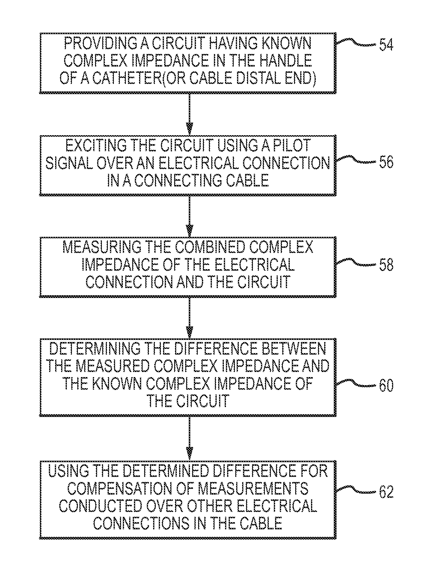
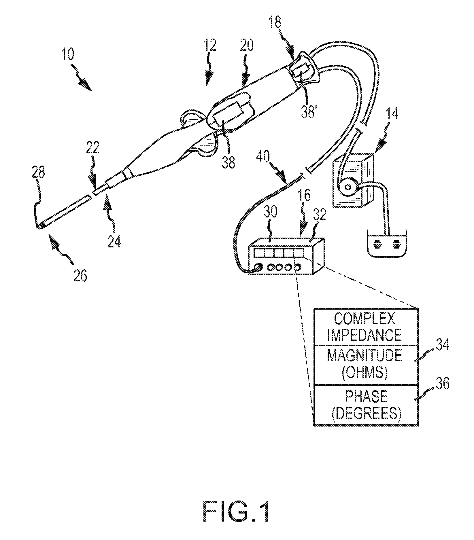
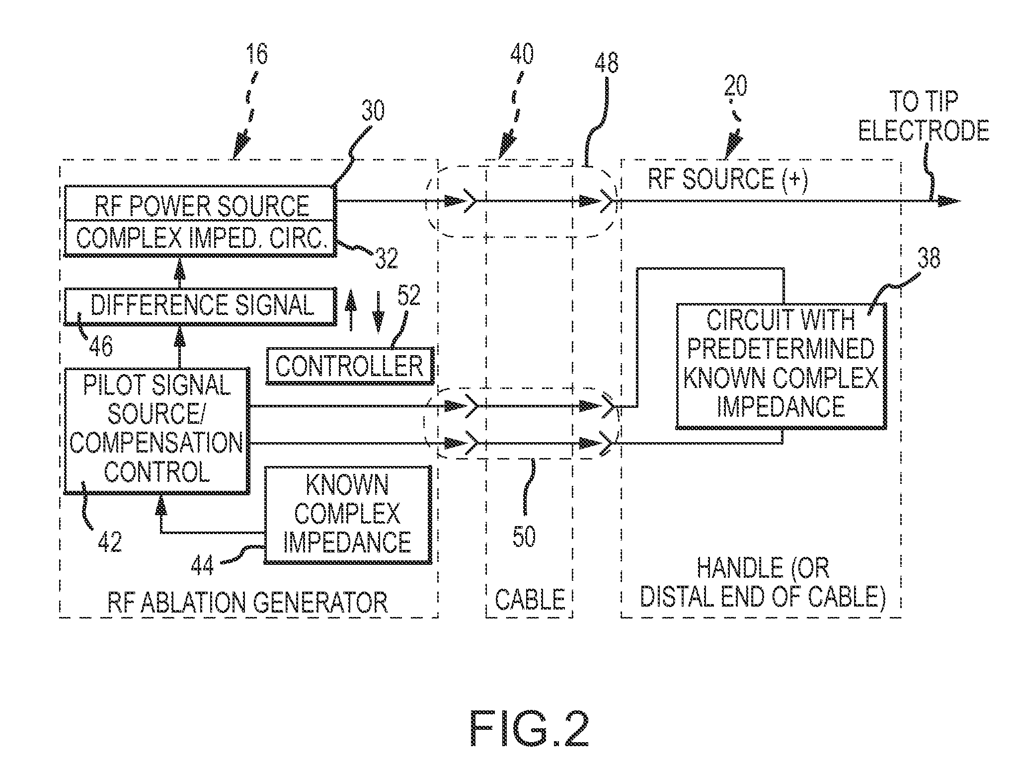
The present invention provides a method and apparatus for measuring the complex impedance of tissue, which can compensate for changes in the equipment, such as cable coiling. The apparatus includes a compensation control that measures the complex impedance of the cable and the circuit, and the difference between them represents variation due to the cable configuration. This difference can be used to compensate for any complex impedance measurements within the same cable. The method also includes measuring the complex impedance between two electrodes, identifying the tissue type based on the measured magnitude and phase angle components, and using this information for diagnosis and therapy of ventricular tachycardia.

Problems solved by technology

RF ablation may generate significant heat if not controlled.
However, one shortcoming in the art is that such measurements are subject to variation due to factors unrelated to the condition of the tissue (i.e., non-physiologic changes).
For example, coiling of an ablation generator cable during the procedure can increase its inductance and thus alter the impedance measurement, resulting in an inaccurate reading that is not completely indicative of the actual tissue condition.
This scenario is particularly problematic where a phase angle of the complex impedance of cardiac tissue is sought, since this parameter is fairly low to begin with (<15°) for the frequencies typically used for RF ablation.
Another shortcoming is that conventional approaches for complex impedance measurements do not provide any intelligence as to tissue morphology, but rather appear to relate to tissue heating and electrode-to-tissue contact levels.

Method used


Image

  • Method and apparatus for complex impedance compensation
  • Method and apparatus for complex impedance compensation
  • Method and apparatus for complex impedance compensation

Examples


Embodiment Construction

[0018]The invention that will be described herein includes two main aspects. In the first aspect, an apparatus and method for complex impedance compensation is provided. The first aspect of the invention overcomes a problem described in the Background, namely, changes in the measured complex impedance that are observed but which are due to changes in the configuration of the equipment, namely the connecting, such as by cable coiling and the like. The first aspect provides the ability to measure the complex impedance with respect to the tissue more accurately, which, as understood by those in the art, will have many useful applications. In the second aspect of the invention, an apparatus and method is provided for determining a tissue type based on, preferably, a phase angle component and / or also a magnitude component of the tissue's complex impedance. The second aspect of the invention is useful in identifying tissue during certain applications, for example, identifying scar tissue ...


PUM


Abstract

A compensation circuit has a predetermined, known complex impedance and is located in a handle of a catheter or in a distal end of a cable that connects to the catheter. The compensation circuit is probed with a pilot signal produced by a compensation control that is external to the catheter, by way of an electrical connection through the connecting cable. The compensation control measures the complex impedance, which is the combination of the circuit's known impedance as well as that of the cable. The compensation control then determines the difference between the measured and the known complex impedances. The difference represents that which is attributable to the cable, and is used to compensate or cancel out such cable-related contributions to complex impedance in measurements made over other electrical connections in the same cable. In another aspect, an unknown tissue is identified as one of a plurality of possible tissue types such as regular myocardium, scar and fat based on the measured phase angle of the complex impedance of the unknown tissue.

Description

BACKGROUND OF THE INVENTION[0001]a. Field of the Invention[0002]The instant invention relates to a method and apparatus for complex impedance compensation, and, in another aspect, a method and apparatus for using complex impedance measurements including a phase angle to detect tissue morphology.[0003]b. Background Art[0004]Many applications have been proposed for the use of a measured impedance of tissue, for example cardiac tissue, and not surprisingly a number of approaches for making such impedance measurements have also been proposed. One procedure where an impedance is measured and used is in cardiac catheter ablation.[0005]As general background, there are a number of methods used for ablation of desired areas, including, for example, radio frequency (RF) ablation. RF ablation is accomplished by transmission of radio frequency energy to a desired target area through an electrode assembly to ablate tissue at the target site. RF ablation may generate significant heat if not contr...

Claims


Application Information

Patent Timeline
Patent Type & Authority Patents(United States)
IPC IPC(8): A61B5/05A61B18/04A61B18/18
CPCA61B5/053
Inventor SCHNEIDER, CLINTON W.
Owner ST JUDE MEDICAL ATRIAL FIBRILLATION DIV
Learn More